
1. Introduction
The importance of unmanned surface vehicles (USVs) and unmanned underwater vehicles (UUVs) has recently increased as various marine resources, such as petroleum and gas, are gaining importance (Bentley, 2002; Nicholson and Healey, 2008). Although massive amounts of resources are present in the oceans, marine exploration is difficult to perform due to ocean currents and weather conditions (Hou, 2013). Particularly, the operation of a UUV in water poses difficulties that are not encountered on land, such as difficulties in supplying power, communication issues, low visibility, and water pressure. Recently, studies on platforms that combine USVs and UUVs have been performed to resolve such difficulties. Sarda and Dhanak proposed a hybrid surface and underwater vehicle (HSUV) that assists in launching and recovering vessels using tether cables (Sarda and Dhanak, 2017). However, this platform is limited in terms of power supply and real-time transmission of large amounts of data. Zwolak et al. proposed a similar platform that can additionally acquire large amounts of data (Zwolak et al., 2017); however, this platform faces difficulties in real-time data transmission and power supply for long-term operation. In addition, it is difficult to obtain the real-time location of a UUV.
To resolve the aforementioned limitations, an HSUV that combines a USV and a UUV, retaining their advantages, is proposed in this study. The USV used is a stable catamaran designed to easily accelerate (Molland et al., 1994). The UUV used is also a catamaran that receives power from the USV, liberating space that would be occupied by batteries and increasing the payload capacity. Sensor data of the UUV can be verified in real time on land through a tether cable, and control commands can be transmitted. The power supplied from the USV enables UUV to be operated for a long period of time using its function for real-time communication with land. In addition, images from the UUV can be acquired in real time on land. The real-time relative locations of the USV and UUV can be identified by utilizing ultra-short base line (USBL) sensors.
The system components, kinetics, and control algorithm of the developed HSUV are described in Sections 2, 3, and 4, respectively. Kinematic performance and control test results from offhshore tests are described in Section 5.
2. System Structure of Hybrid Surface & Underwater Vehicle
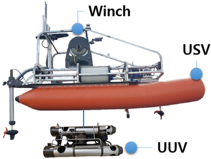
Fig. 1 shows the structure of the HSUV constructed for this study. Operation console commands are transferred to the USV and UUV via a hub through wireless bridges, and USV and UUV are connected through a tether cable. The total weight of the HSUV, excluding the operation console, is 350 kg.
2.1 System Components of the Hybrid Surface and Underwater Vehicle
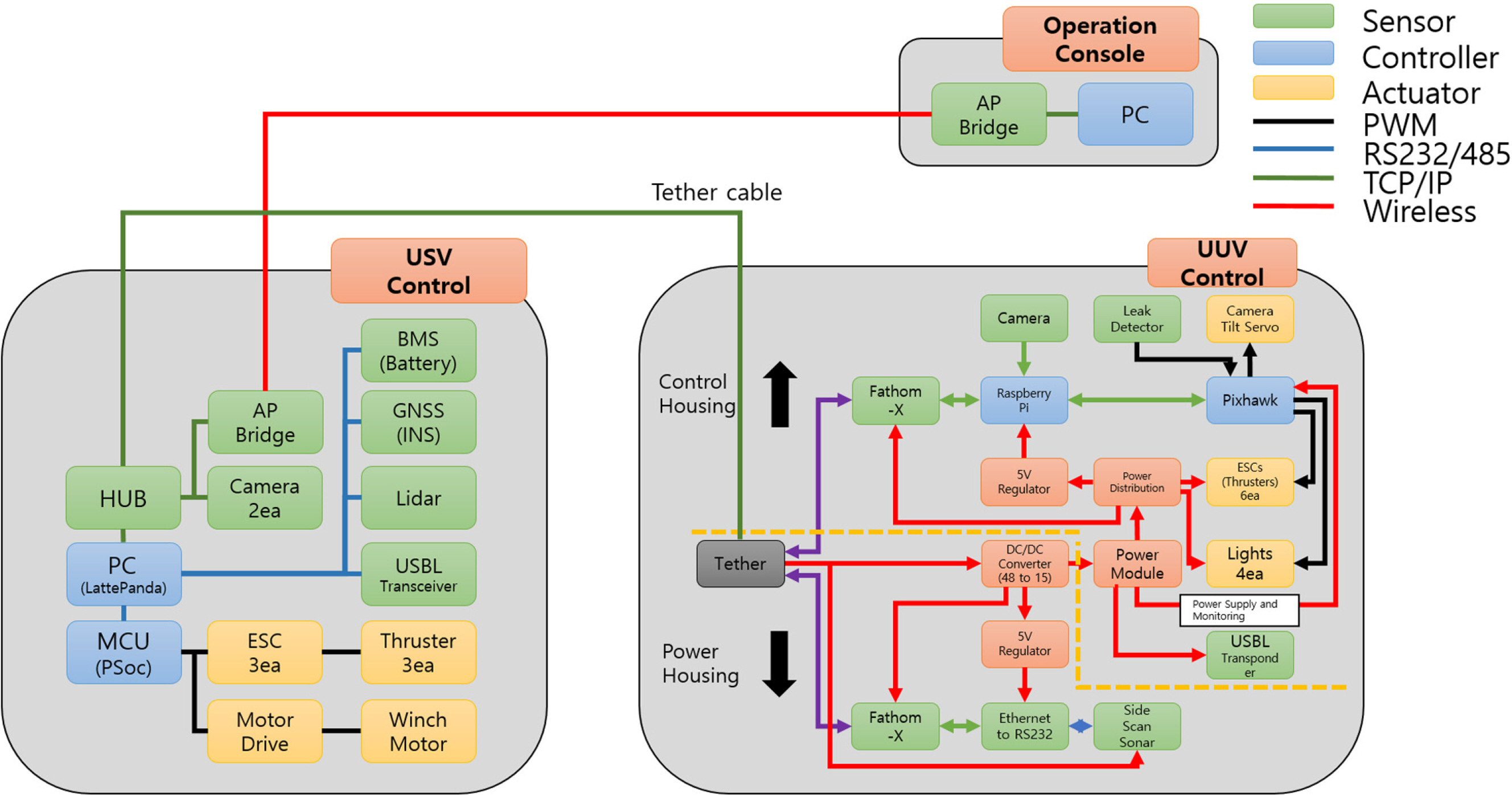
The system of the HSUV was constructed as in Fig. 2, and the console was constructed to control it. A personal computer (PC) in a land station has a program written in C# to identify the real-time condition of the surface and underwater vehicles via a graphical user interface (GUI). The main controller of the USV uses CYBCKIT-059 PSoC to operate the propellers, and the code was written to autonomously sail based on global positioning system (GPS) and attitude and heading reference system values. The surface vehicle is equipped with two cameras, a battery management system (BMS), a USBL, and light detection and ranging (Lidar), which can be verified on the operation console. The main controller of the underwater vehicle uses Pixhawk, and the cameras and side scan sonar data can be verified in real time on the operation console.
2.2 System Components of Unmanned Surface Vehicle
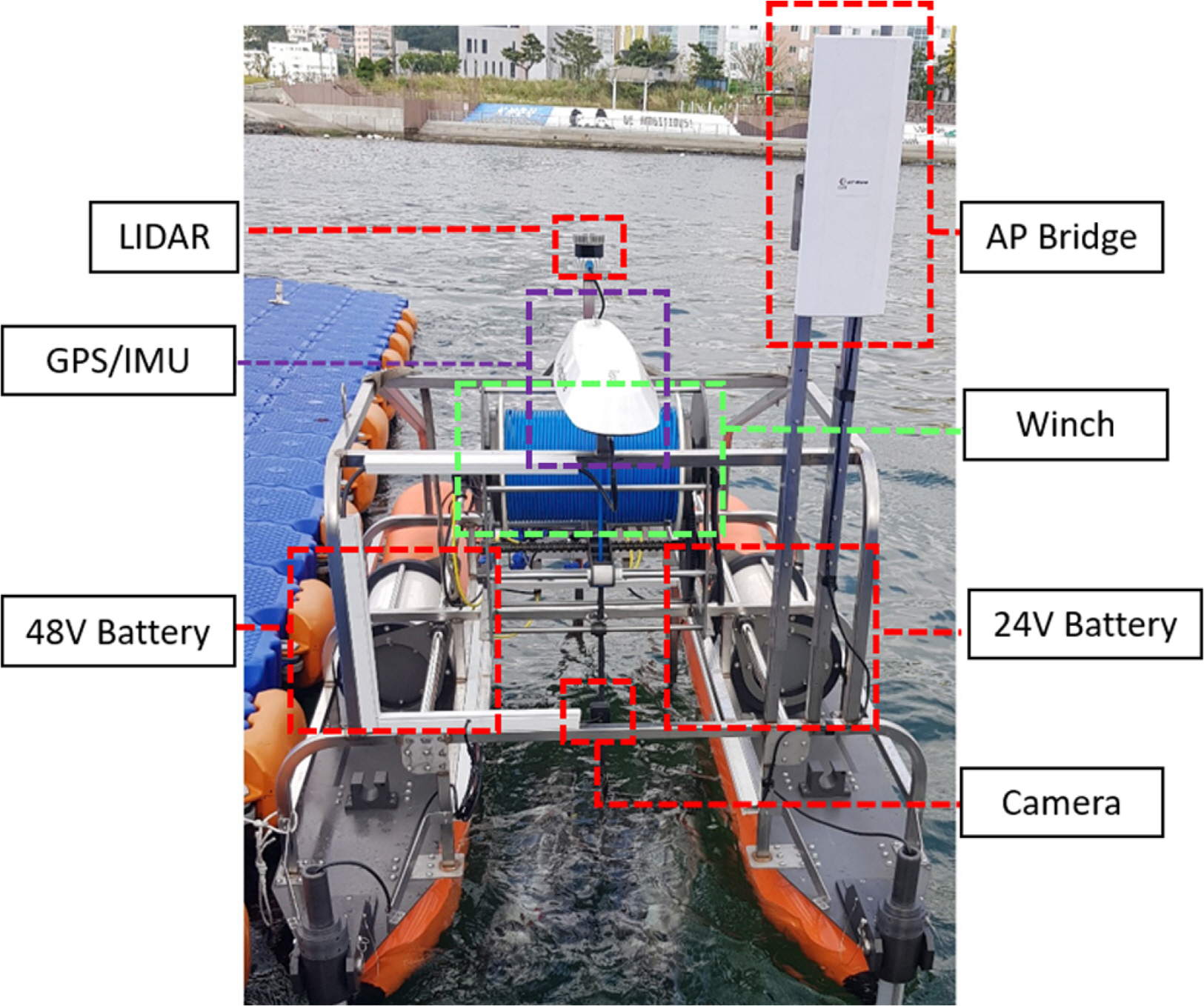
The components of the USV are shown in Fig. 3. The USV is a stable catamaran that has a buoyancy gain and can quickly accelerate. It transports the UUV to an exploration point by realizing GPS location information-based autonomous sailing. Voltage decreases and efficiency are considered to install batteries of 48 V and 24 V in the USV. The winch system of the USV consists of a brushless direct-current motor, a slip ring, and a level shaft. This system stably winds the tether cable, supplies electric current to the UUV, and controls exploration depths. The lidar and camera sensors were attached to recognize obstacles. The Lidar is capable of 360┬░ omnidirectional identification. Front and docking verification cameras provide visual assistance in operation. The specifications of the USV are listed in Table 1.
2.3 System Components of Unmanned Underwater Vehicle
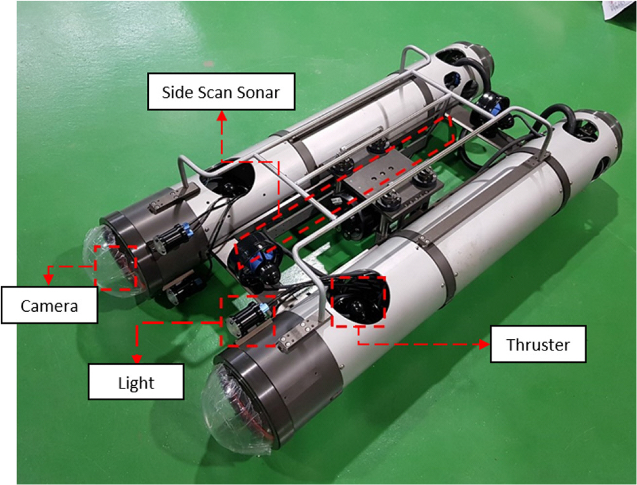
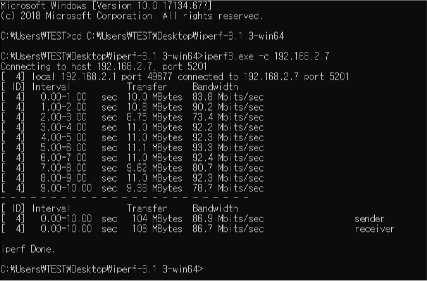
Fig. 4 shows the UUV components. The UUV has an underwater tilt camera and a side scan sonar as sensors for exploring seabed terrain and underwater structures. The UUV weighs 49.5 kg on land and has a negative buoyancy of 14 kg. It is constructed in the form of a catamaran with relatively stable rolling to acquire high precision data from the side scan sonar. Depths are controlled using the depth sensor-based winch system and six propellers are used in the hull to allow six-axis control. The kinematic performance and USBL data are used to accurately identify the location of the underwater vehicle and perform various tasks. Ethernet is used for data transmission, and the data transmission rate to/from the land station is approximately 86 Mb/s. This value is verified using the iperf program, as shown in Fig. 5, and the data of each sensor can be verified in real time at the land station. The underwater camera is mounted in the dome-shaped space on the front of the underwater vehicle and its direction can be adjusted up to 90┬░ using a tilt servo motor. It is a low-light camera for exploration in dark water and has horizontal and vertical visual fields of 80┬░ and 68┬░, respectively.
Considering voltage decreases through the tether cable, the underwater vehicle received 48 V direct-current power. Data are transmitted between the surface and underwater vehicles through the tether cable via power over Ethernet. A light whose brightness can be adjusted up to 1,500 lm was attached for dark underwater exploration.
2.4 Operation Console and GUI Program
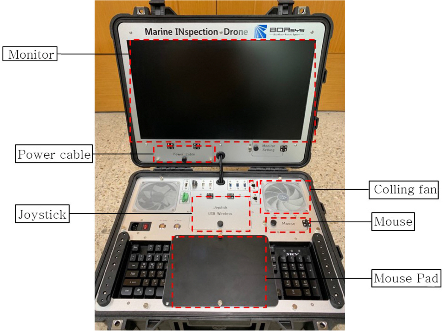
Fig. 6 shows the operation console of the HSUV. The operation console was built to verify side scan sonar data, cameras, and the current states and control commands of the USV and UUV in real time. A commercial PC, a joystick, and Wi-Fi equipment are loaded in a case, and an inverter is mounted inside the console to supply power to access point (AP) bridges. The console has sufficient space to efficiently store the power cable, mouse, and joystick required for operation. A cooling fan was also attached, considering the strong direct sunlight on the sea.
Fig. 7 shows a part of the operation program used in this study. This program was written to verify numerical data of surface and underwater vehicles and GPS and intuitively view the data via GUI. Google Map is provided to verify real-time locations and paths. Joystick, way point (WP) and dynamic positioning (DP) modes, and winch control are implemented as functions of the program. The four cameras of the HSUV are connected to the operation console via dual monitors to conveniently monitor their output.
3. Kinetics of Hybrid Surface and Underwater Vehicle
The dynamics of the HSUV is based on the NewtonŌĆōEuler equations and vectors. The USV moves along the x-axis and y-axis; hence, its motion can be expressed as surge, sway, and yaw. The notation associated with each axis is presented in Table 2. Considering the Coriolis centripetal force and attenuation acting on the USV, the dynamic equations can be expressed as Eqs. (1)ŌĆō(3). The detailed definitions for the parameters and states are described in Fossen (2011) and Cho et al. (2020).
Here, m is the mass, I is the mass moment of inertia, and Žä is the thrust of two rear thrusters attached to the USV.
Eqs. (4)ŌĆō(6) represent the motion of the UUV. The UUV follows the considerations for USV, but surge, sway, and yaw are considered as relative locations and relative direction angles. The subscript R in Eqs. (4)ŌĆō(6) was used to avoid confusion with the equations of the USV. The symbol on the right side of sigma represents the sum of environmental disturbance and thrust.
4. Control Algorithm of Hybrid Surface and Underwater Vehicle
4.1 Dynamic Positioning Algorithm
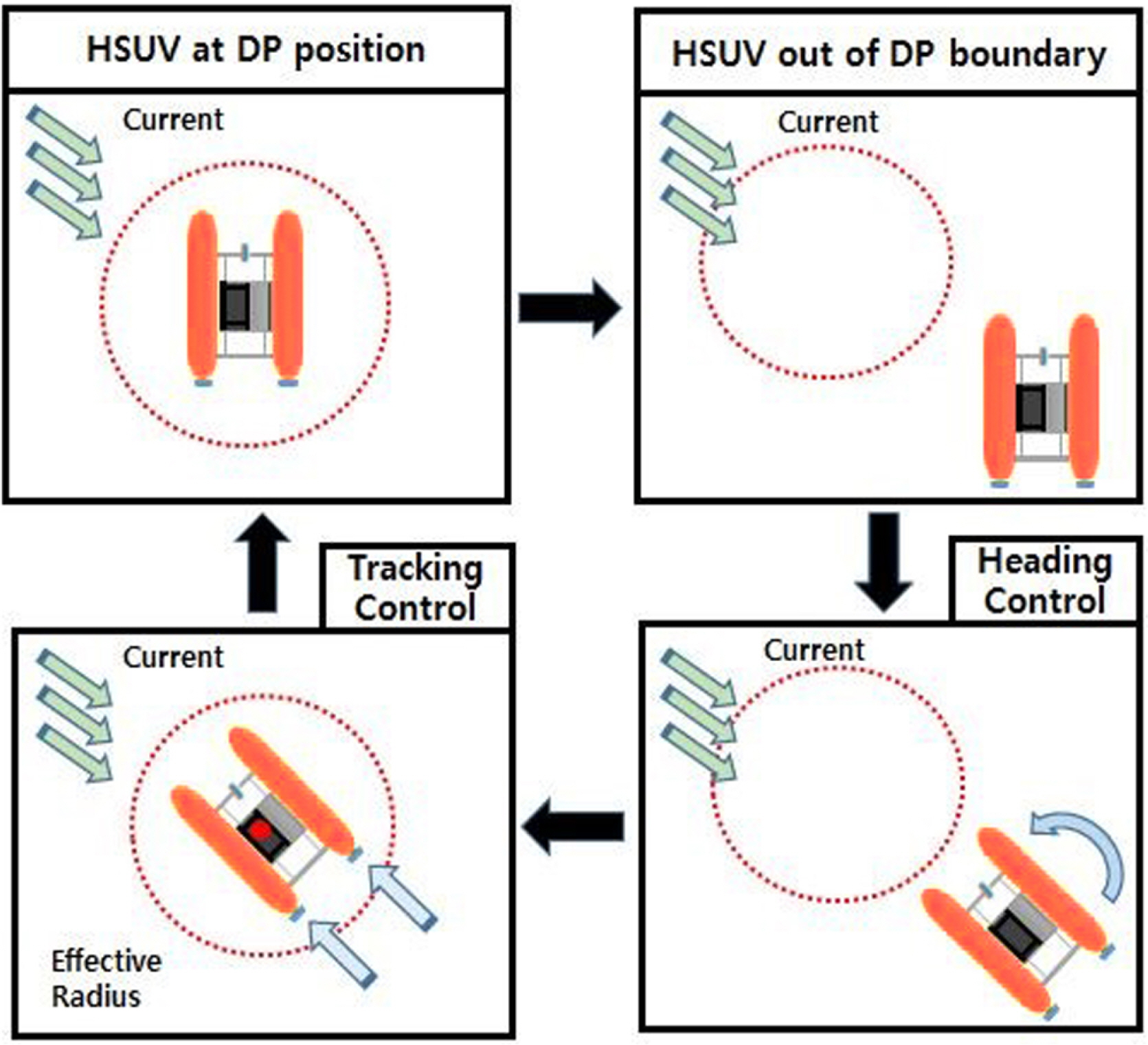
The DP algorithm of the USV is illustrated in Fig. 8. The DP process is performed as follows: when the USV moves out of a target radius due to the effect of tidal current or wind, it obtains its rotational direction angle toward a DP point and adjusts its heading. The platform moves when the heading of the platform coincides with the target direction angle, and stops when it reaches the target point.
Eq. (7) represents the distance error. [X(t), Y(t)] represents the location of the HSUV, represents the target point location, and Žüc is the target radius.
4.2 Way Point Algorithm
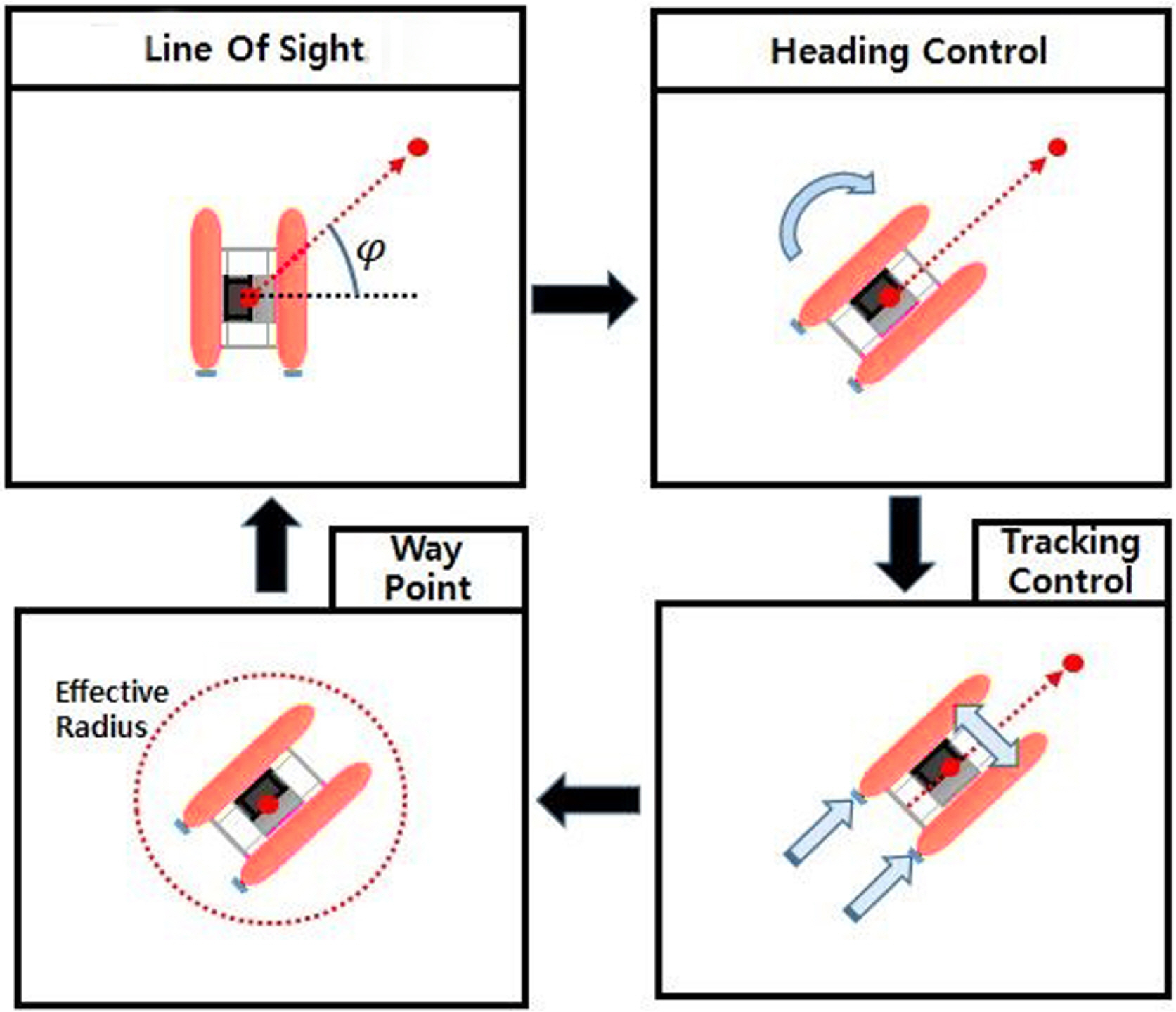
The WP algorithm is illustrated in Fig. 9. When the latitude and longitude of a target point are given, the USV obtains its target direction angle using the line of sight and adjusts its heading. The platform moves when the heading of the platform corresponds to the target direction angle, and stops when it reaches the target point. This process is completed and repeated toward the next WP.
Eq. (8) represents the direction angle error. [X(t), Y(t)] represents the location of the HSUV, and [Xk, Yk] represents the target point location.
5. Offshore Tests
Offshore tests were performed on the relatively calm coast of the Korea Maritime and Ocean University to evaluate the performance of the proposed HSUV and its control system. The offshore tests include accuracy tests of the GPS, which is the key sensor on land, and communication tests. Based on these tests, route tracking tests of the USV, DP, and performance tests of the side scan sonar were performed.
Tests for the communication distance of the platform were performed prior to the main tests. The communication equipment used in the unmanned vessel has a high effective transmission rate of 360 Mb/s and additionally uses an omnidirectional antenna.
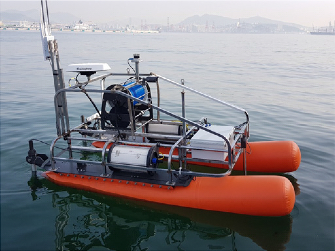
The test results indicated that data are effectively received and transmitted up to 890 m in the absence of obstacles between thewireless communication devices. Fig. 10 shows a picture of the offshore tests performed.
5.1 GPS Sensor Tests
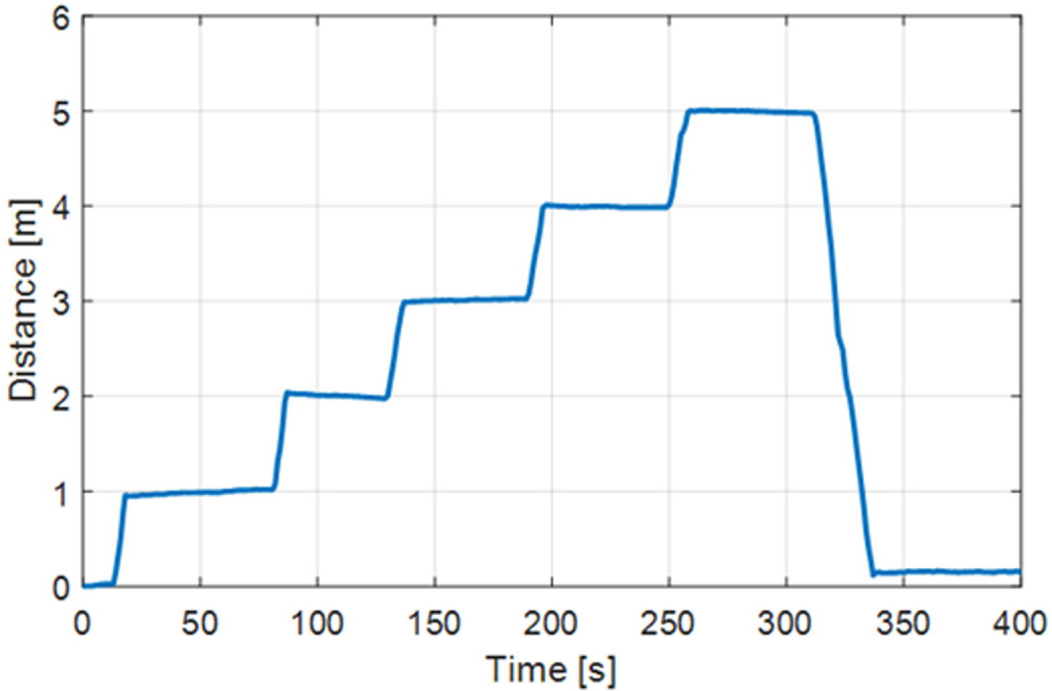
The GPS sensor used in the proposed hybrid system provides true north data, magnetic north data, and altitude values. Tests for moving the system 5 m and then returning to the initial point were performed to verify the reliability of sensor values. The test results are shown in Fig. 11.
5.2 WP Tests
Route control tests were conducted on the USV to individually evaluate the accuracy of the sensors.
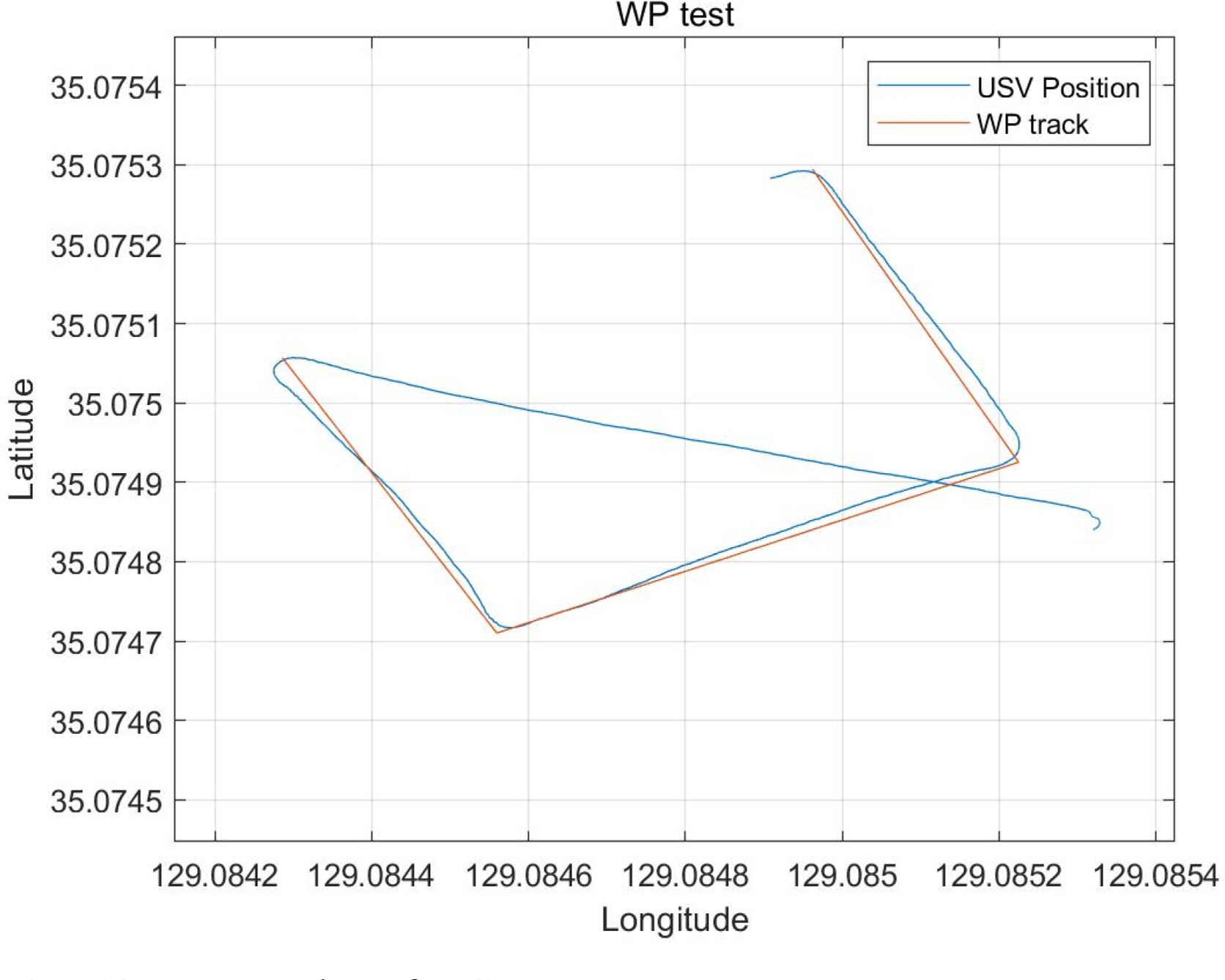
The WP algorithm of Section 4.2 was used for the USV to reach four WPs on the sea in these tests. Fig. 12 shows the corresponding results, and Table 3 lists the WPs designated in the operation console. The latitude and longitude of the four WPs were input into the operation console and WPs 1ŌĆō4 were reached from the start point. The maximum error obtained for the WPs was 2.6 m.
5.3 Side Scan Sonar Performance Tests
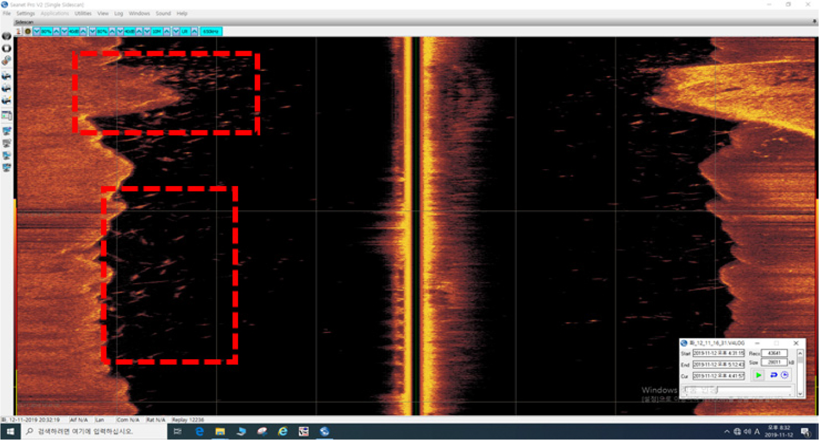
A side scan sonar was mounted on an underwater drone to measure the state of the bottom of a river. The tests were performed on the estuary bank of the brackish water zone of Nakdong River. As the river is not deep, the UUV was lowered 0.5 m, towed by the USV, and moved straight-line distances. Fig. 13 shows pictures of captured bridge posts and fishes.
5.4 Dynamic Positioning Tests
The DP algorithm of Section 4.1 developed for this study was used to perform the DP of the USV on the sea. The DP algorithm was constructed to operate the controller when the USV moves out of a target radius of 3.0 m to extend the operation time of the USV. With the algorithm, the 3.3 m USV was controlled to remain within a certain radius. Fig. 14 shows the results of ten minutes of DP in measurement units of 500 ms. The test results generally satisfied the target error radius of 3.0 m, and the average DP error was 2.03 m, which shows that DP was adequately performed in comparison to the full length of the vehicle.
6. Conclusions
In this study, the structure and control system of the HSUV were designed and constructed and basic performance tests were performed. The sensor data of the USV and UUV can be verified in real time through the tether cable, and the UUV can be used for a long period of time. The individual sensor performance tests were performed, followed by offshore tests using the controller algorithms constructed in Section 4 to verify the performance. The maximum error of the WPs of the USV was 2.60 m, and the average DP error was 2.03 m, which indicates the excellence of the control system. In addition, the side scan sonar of the UUV was used in the same sea area to explore the bottom of a river. The river, surrounding terrain, and fish search information could be monitored in real time at the land station by utilizing the real-time communication system.