
1. Introduction
A ship mooring system is a device that secures a vessel at a berth or during mooring operations to minimize the impact of waves. Offshore mooring lines secure an offshore floating structure during mooring operations, and they are capable of withstanding additional loads from movements due to wind, waves, and currents, with guaranteed durability over long-term use, thus serving as an essential component in offshore operations. Mooring lines are used not only for floating offshore wind turbines, but also for offshore plant equipment, as well as for securing offshore structures such as semi-submersibles, tension leg platforms (TLPs), and floating production storage and offloading (FPSO). With the broad range of potential applications, there has been continuous research on the development of mooring methods worldwide, including in Korea. The main functions for achieving load control of the mooring rope for securing offshore structures include pay out/heave in, auto tension, securing/braking, and in the case of auto-tension, pay out/heave in operations are repeatedly performed to maintain constant tension of the mooring rope (Lee et al., 2012).
According to these operational characteristics, there have been both large- and small-scale incidents and casualties, and there is a pressing need to ensure the safety of equipment as countermeasures against the incidents. To this end, a commonly used method that is employed for the protection of the mooring rope and equipment is to monitor and manage the load using load cells that measure torque and tension such that the tension is kept below a certain level. In the case of a mooring rope, operational problems that may affect safety are mainly known to arise in the areas of the eye and splice, which are the parts that serve the important function of making a joint for successive ropes, and which are processed manually. In general, when mooring forces are measured using a load cell that measures tension, the load cell is mounted on the top or end of a mooring line to measure the average value; in this way, it is not possible to detect a load that has a concentrated distribution in the center, eye and splice parts of the mooring line.
In terms of the method employed to measure the rope tension using a load cell, the linear stress response characteristics can be used as much as possible in the case of chains and wires made of metals. However, in the case of synthetic mooring ropes, there are changes in stiffness due to the creep phenomenon that occurs when the ropes are used. Therefore, in the conventional load cell method that performs measurements using the linear stress response characteristics, there is a technical limitation in terms of determining the durability. For this reason, in the case of synthetic mooring ropes, they are used by significantly increasing the safety factor, or are discarded after a certain period regardless of the in-service history. Therefore, various approaches in research and development have been made for mooring ropes that allow load detection, and in recent years, there have been new technologies that incorporate mooring ropes/chains using sensor and smart IT technologies for monitoring methods with a load detection function composed of steel wires and chains. In addition, there have been demands for this type of function in the area of offshore wind turbines.
There has been mounting interest in the development of technology that is capable of integrating a number of sensors with smaller sizes, and which perform measurements of physical properties by connecting many sensors to continuous cables that enable the transmission of signals over a long distance between the sections where the sensors are installed. In this study, the use of the proposed sensor enables measurements of most of the physical quantities that need to be measured, as well as a simplification of the system constituting the sensor. For a comprehensive review of the general characteristics of fiber optic sensors, please refer to the (Culshaw et al., 2008). In this case, measuring equipment with sensors was designed, fabricated, and validated in various forms depending on the type of application. The widespread application of fiber optic sensors began after research on fiber Bragg grating (FBG) sensors started in the late 1990s (Meltz et al., 1989; Hill and Meltz, 1997).
In the theory of FBG, the reflected wavelength is determined by the refractive index modulation and of the core and the grating period. Eq. (1) represents this relationship as follows
where
When the grating period expressed in Eq. (1) is subject to an external force, linear length changes occur. Accordingly, the Bragg wavelength changes and the applied force are analyzed using the measurement of the changes in the wavelength. External forces are physical quantities composed of various factors such as temperature, pressure, strain, noise (sound), vibration, acceleration, and the slope. The sensor is made in the form of a probe to measure physical quantities with increased sensitivity to show linear changes of the grating period. For the sensor used in this study, a grating was designed by selecting the reflectance and reflected wavelength of a single-mode fiber optic, and the measurement equipment was implemented (Lee and Kim, 2011).
2. Materials and Methods
In previous studies, the applicable range of a mooring line is set by measuring the minimum breaking load (MBL) through a tensile load test by fabricating an actual mooring line after analyzing the material properties. With respect to the form of the mooring line for application in theoretical analysis, different forms of the mooring line are used in actual applications and for theoretical analyses, and it is difficult to apply the result of theoretical analysis to real-life outcomes, indicating a considerable difference between the theoretical analysis and the practical applicability. The mooring lines are often regarded as having a simple structure with several threads twisted, but in practice, the axial stiffness, coupling stiffness, and torsional stiffness of the mooring line exhibit different behaviors depending on the characteristics of the materials or changes in the type and degree of the twisting. The mooring lines are made using processes in the order of yarns-twisted threads-strands-ropes, and the final strength and wear resistance of the mooring line are significantly affected by the method and degree of the twisting in each process (Kim et al., 2018).
In practical applications, when the synthetic mooring ropes made from polymer materials are used to secure a vessel, the above characteristics lead to breaking of the rope; this is not observed in steel wires and chains, and the MBL is gradually reduced owing to non-linear changes in stiffness. The breaking of synthetic mooring ropes significantly affects the service life of the rope, and the main reason for the breaking is fatigue failure. The breaking appears in different patterns depending on the materials of the synthetic mooring rope. The A-type synthetic mooring rope is vulnerable to humidity, the B-type rope is vulnerable to creep, and the C-type rope is vulnerable to compressive fatigue failure; these are the main causes of breakages of ropes, and these factors determine the design and service life of the mooring lines. Creep is a phenomenon in which molecules gradually elongate when a synthetic mooring rope is used for a long time with a constant load applied to the rope made of combinations of polymers. In mooring lines exhibiting the creep phenomenon, it is very important to observe and monitor whether the creep occurs continuously owing to the applied loads, and it can lead to the breaking of the rope. The creep phenomenon leads to the permanent elongation of the synthetic mooring rope owing to temperature, time, and loads, and may occur in all synthetic mooring ropes. It has been reported that the pattern of creep occurrence and corresponding result values differ depending on the type of the synthetic mooring ropes (Park et al., 2017).
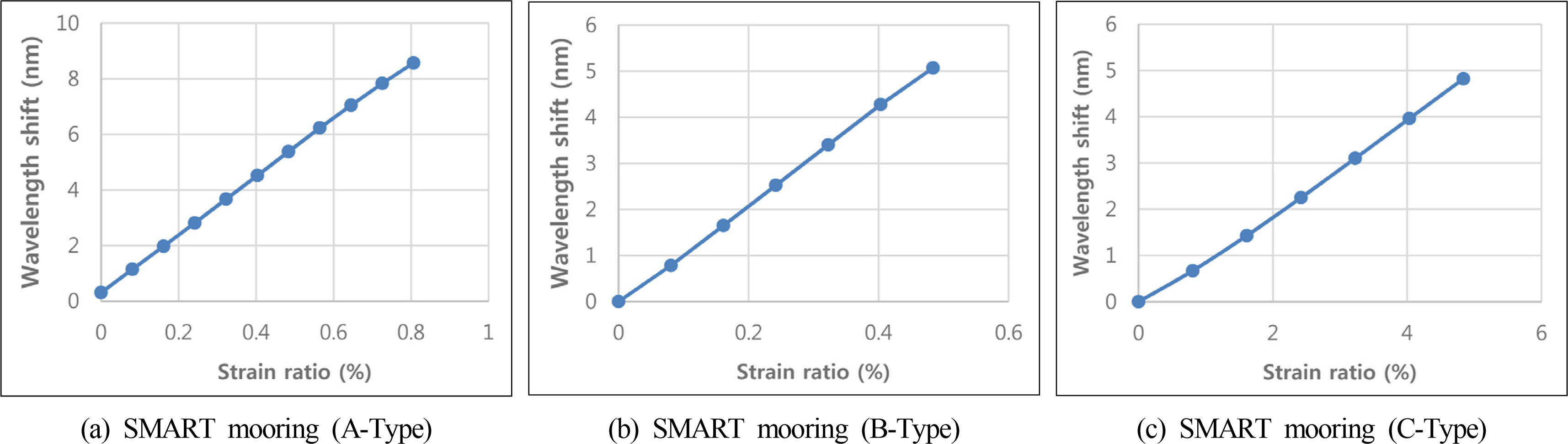
In order to understand the characteristics of a Smart Mooring and Riser Truncation (SMART) mooring line with fiber optic sensors, basic properties were examined by manufacturing the mooring line with a diameter of about 3 mm. Using the multi-core fiber twisting device manufactured by CyTroniQ, fiber materials of A, B, and C types were integrated with the sensor of CyTroniQ Co., Ltd., which was introduced in the Introduction. The mooring line, which is integrated with the fiber optic sensor, was equipped with a sensor that responds to the external load, and is defined as a SMART mooring line. The developed system is characterized by arranging sensors in series so that the sensors can respond to a load that is applied partially to the mooring line. A strain test was performed on a mooring line with a diameter of 3 mm and a test length of 124 mm, and the following results were obtained. Fig. 1 shows the experimental results that examine the sensor response according to the change in the length of SMART mooring. The polymer materials used for the rope are A-Type, B-Type, and C-Type.
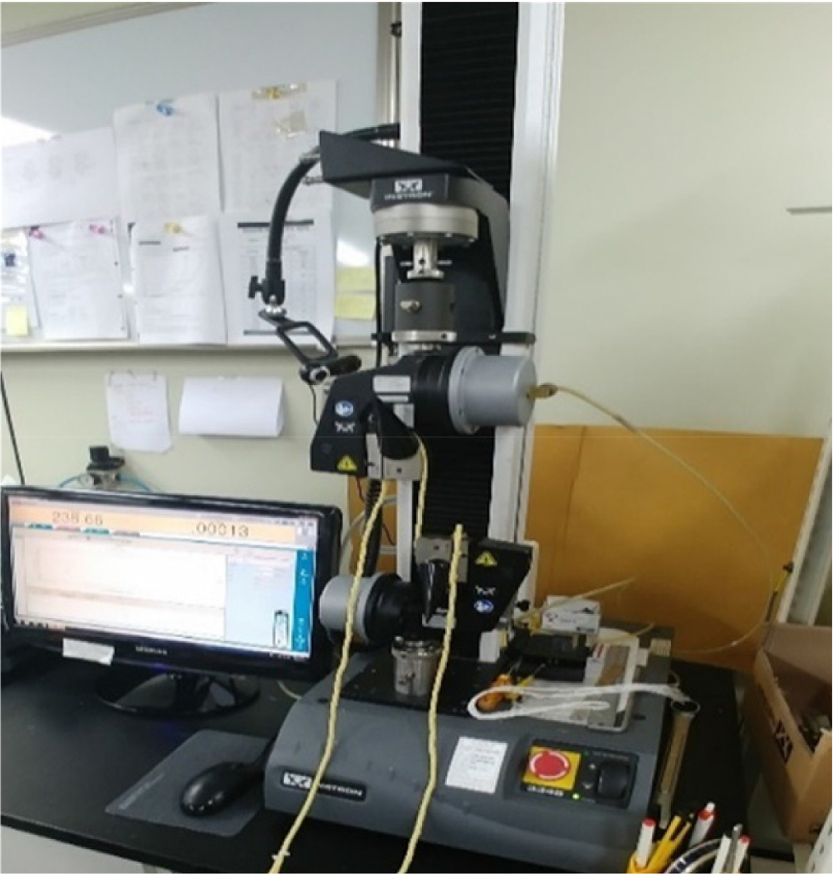
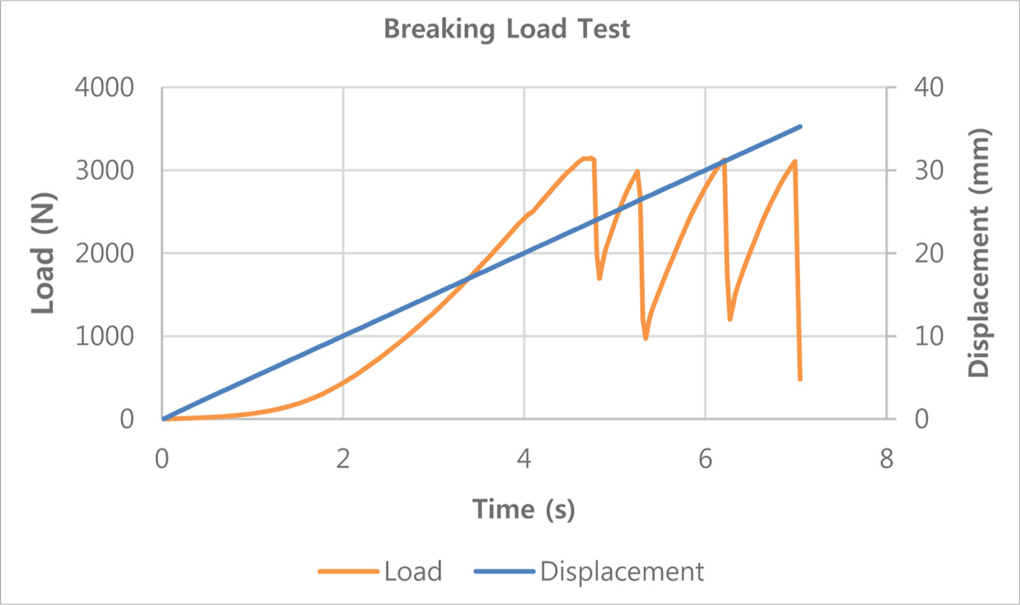
As shown in Fig. 1, with changes in the length of the mooring line, SMART mooring composed of A-Type material exhibited a wavelength shift of 8 nm with changes in length of up to 0.8%. SMART mooring composed of B-Type and C-Type materials exhibited a wavelength shift of 5 nm with a length change of 0.5%. In addition, the variation in the linear response characteristics of thesensors with the given changes in length were confirmed regardless of the materials, and according to the results obtained, the performance of the sensor was sufficient to conduct the breaking load test. Fig. 2 below shows the relationship between the universal test machine (UTM) and SMART mooring made of C-Type material to conduct the breaking load test. The tensile strength test was performed according to the standard of KS K 0412, and according to the change in length at a constant rate, the load was measured and recorded. The result of the tensile breaking load is shown in Fig. 3. From the results in Fig. 3, the increased length was 23.7 mm, exhibiting an elongation of 9.48%, and at this time, the maximum load was 3,145 N.
The SMART mooring fabricated as above was applied after deformation and length design for use in the water basin test under the application of the scaling law. The results obtained from a scaled model experiment for the determination of parameters such as diameter ratio, stiffness, and length for the application of the scaling law to conduct the water basin test at 1/100 scale are discussed in a separate reference. (Bergdahl et al., 2016).
After confirming the potential applicability of the SMART mooring through a preliminary study with designs including smaller diameters as above, the main test was designed by fabricating the SMART mooring on an actual scale. For the B-type synthetic mooring rope, a product made by manufacturer D was used. For use in the mooring system of the offshore plants, Manufacturer D developed a B-type synthetic mooring rope for a mobile offshore drilling unit (MODU) and one for permanent mooring in sequence, with improvement in creep occurrence in the B-type synthetic mooring rope. In this study, because both a temporary mooring system and a permanent mooring system are used, the products above were selected accordingly, and the variations in the creep characteristics of the B-type synthetic mooring rope with the experiment are presented in another study (Park et al., 2017).
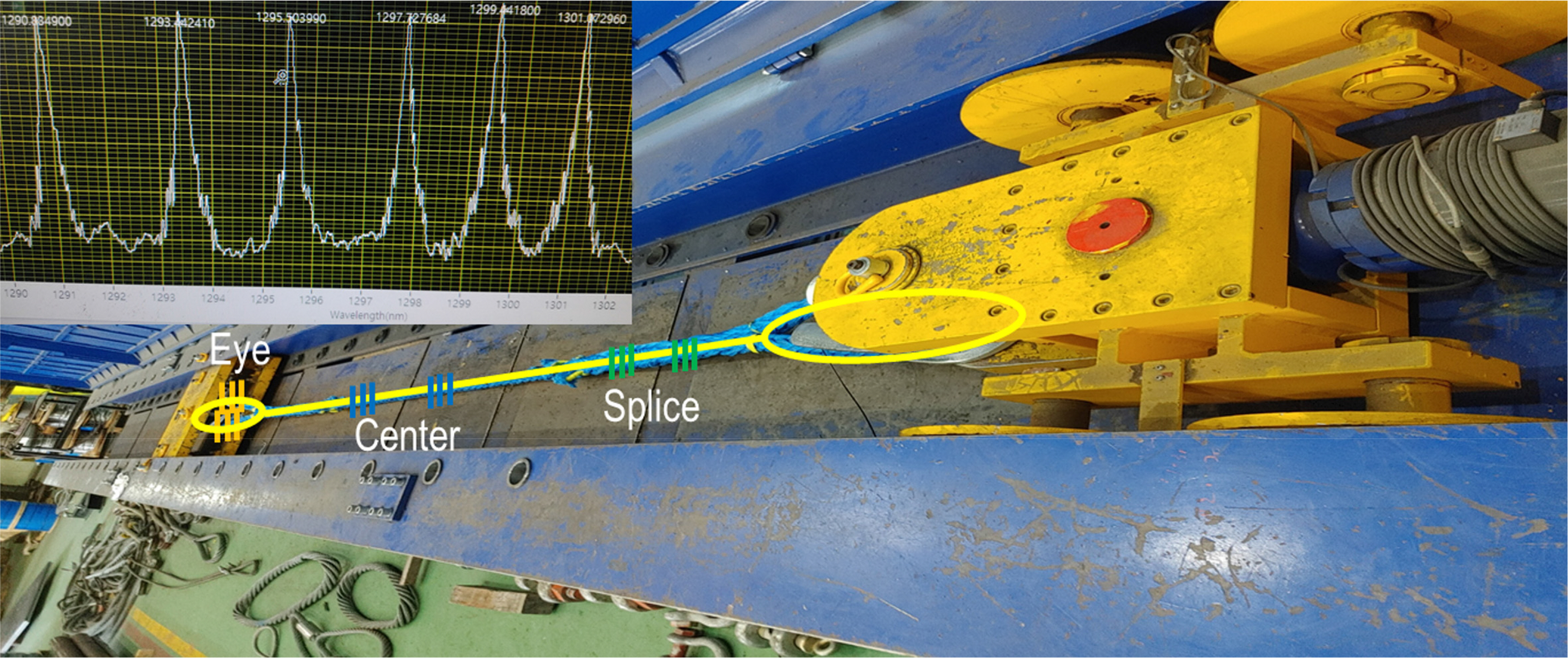
After implementing the SMART mooring, a red light source was connected to the fiber optic inside the mooring line, and it was possible to examine the characteristics of light transmission to the opposite side. In order to implement the real-world SMART mooring, mooring rope with a diameter of around 54 mm (2-1/8 inch) and MBL at 186 t (411,000 lbs) was used, and the length of the fabricated SMART mooring was 6.33 m. Sensors were installed in key areas to make joints between ropes, namely the eye, splice, and center, to enable us to investigate the characteristics of the developed system. As shown in the picture in Fig. 4, the fiber optic sensors were integrated into the mooring rope, and a dedicated UTM was used for the tensile load test of the mooring rope. A tensile load of up to 100 t was applied, and the results were obtained at this point for analysis. The static tensile load and dynamic fatigue tensile load tests of the mooring rope were conducted according to the test method specified by ISO 2307, and the longitudinal tension and load were controlled using UTM. The test was conducted in the presence of LloydŌĆÖs Register. The changes in the wavelength of the SMART mooring connected to the load testing equipment were monitored during the tensile load test using a fiber optic sensor measurement unit (interrogator) (Lee and Kim, 2011).
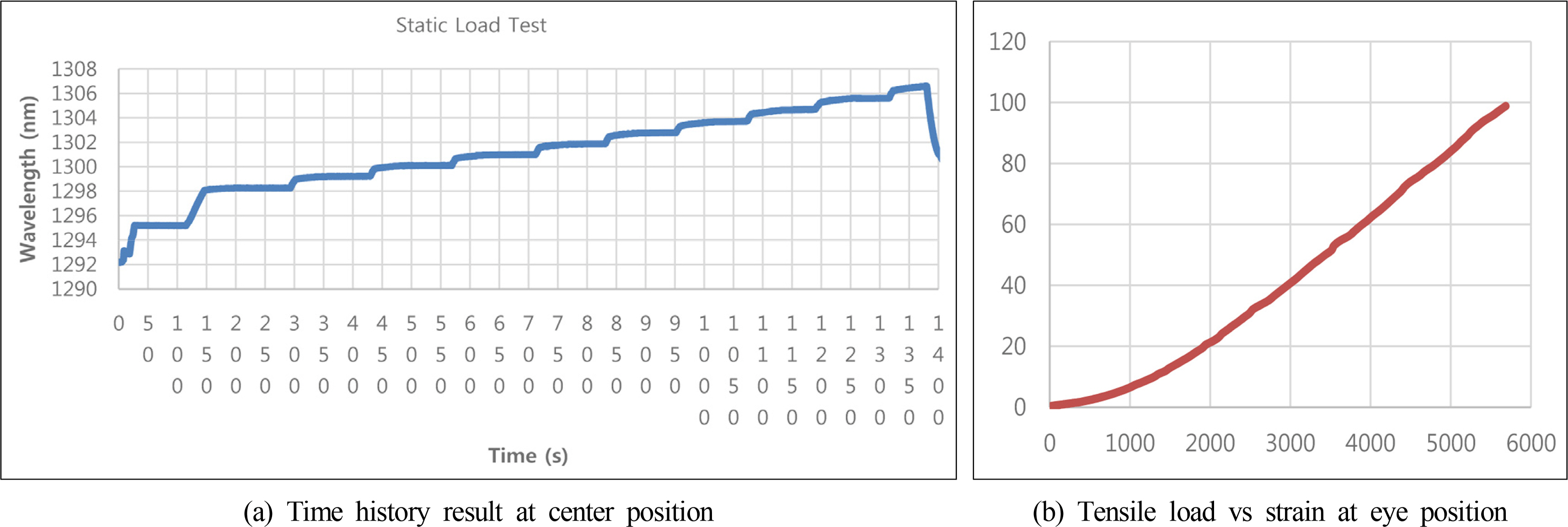
Fig. 5(a) shows that with the SMART mooring, the longitudinal tension is changed to divide the tensile load into 10 levels, and the tensile load test was conducted with a maximum tensile load at 100 t. The response of the sensor in the mooring rope showed a linear change according to the load, and the linear response of the sensor was also measured in the maintained load state. In addition, it was confirmed that the sensor response changed in the same way with the increase in the load. As the load increased up to 100 t, the wavelength increased by 14 nm according to the sensor response, confirming that the response in the sensor changed in the same way according to the tensile load. Next, the variation of the strain according to the tensile load for the sensor connected to the eye position is depicted in Fig. 5(b).
Next, we present the result of the dynamic tensile load test obtained by measurements with a sensor connected to the eye position. The cyclic tensile load was applied 100 times from 30 to 100 t, and the wavelength shift generated at this time was measured by the sensor. The results are shown in Fig. 6, which confirmed that with the application of the cyclic tensile load, the initial wavelength value showed a gradual increase. This is a typical characteristic of a mooring rope made of polymer materials, and by reflecting this characteristic, the sensor shows the same typical characteristic. Based on these results, it is expected that the findings of this study are utilized as instrumental data to determine the durability of SMART mooring according to cyclic loading. After the mooring rope is actually installed on-site, it is considered that the load data can be continuously measured to monitor the response of the mooring rope, and with the accumulation of the associated data, the developed technology can be used to determine the remaining service life.
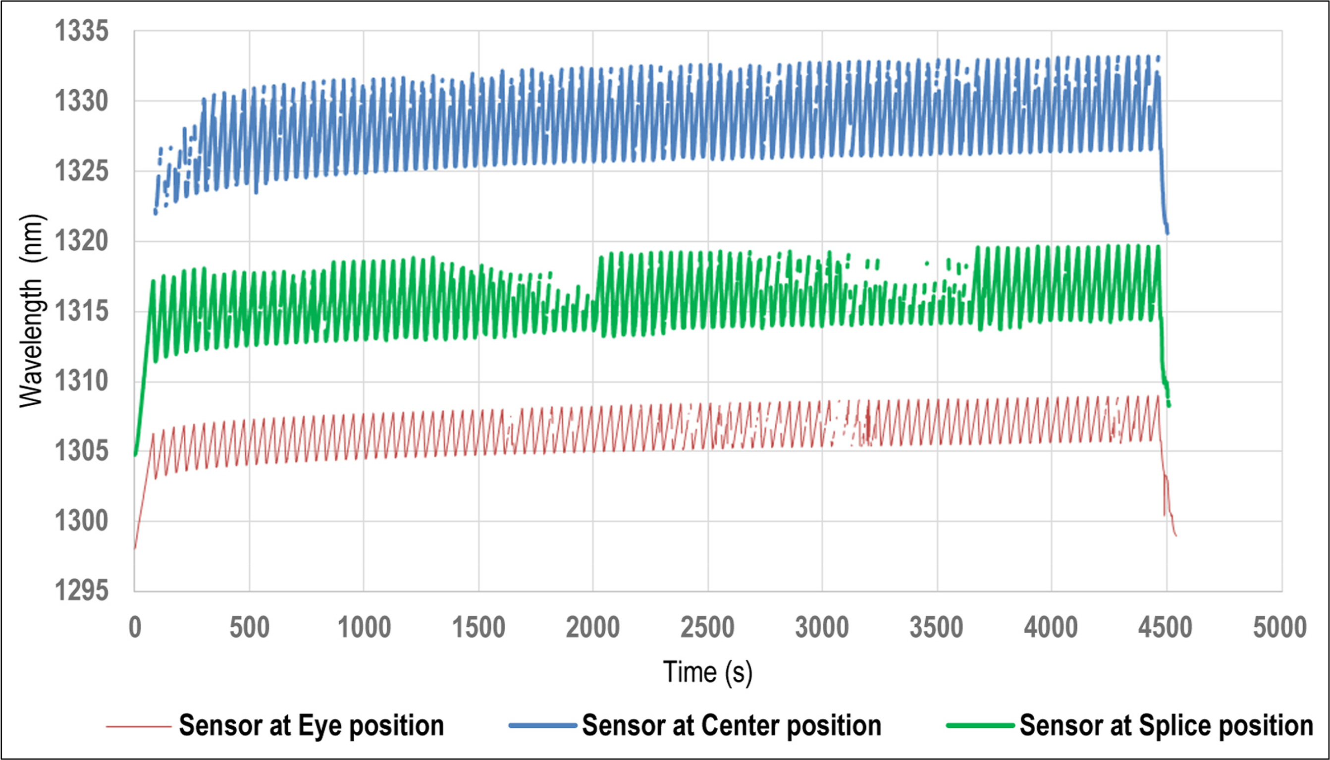
Fig. 7 shows the results of measuring the wavelength shift, that is, the strain, in the eye, center, and splice positions of the SMART mooring during the cyclic tensile load test when a load of 30ŌĆō100 t is applied 100 times in the time domain. From the results, it was confirmed that sensors show responses according to the cycling loading in the eye, center, and splice positions, respectively. From the results of the measured strain, the magnitude of the strain differed depending on the sensor position. The center position showed the largest strain, followed by the splice position and the eye position with the smallest strain. This is believed to be related to the cross-sectional area of the SMART mooring structure subject to the tensile load. The strain at the center position, which is the position with the smallest cross-sectional area of the SMART mooring subject to the tensile load, was about twice as large as the strain at the eye position, whether the material in the center position was used to make a ring in the eye position, leading to the cross-sectional area for the longitudinal tension being twice as large as that of the center position. Further, in the splice position, the strain slightly smaller than that in the center position was measured. From the values of the strain measured in the eye, center, and splice positions, a gradual wavelength shift to the larger values was observed, and it was possible to differentiate between the loads for each position. It was confirmed that the elongation of the final SMART mooring increased from the initial 6.33 m to 7.08 m, which is an increase of 0.75 m, according to the cyclic tensile load of 30ŌĆō100 t. The result showed a clear difference from the characteristics of restoring force in general metals.
3. Summary and Conclusion
This study focused on an area of research that is different from previous studies, and SMART mooring was designed and implemented. The results of the tests conducted in this study are outlined in Table 1 below.
In the case of mooring lines, operational problems mainly occur in the eye and splice regions, which are the parts that serve an important function of making a joint for successive ropes, and which are processed manually. In a structure characterized by a continuous connection with a single material without interruption, when the local cross-sectional area encounters a change, the suitable load detection in the mooring line was not possible in terms of technology employed to measure the local tension. In order to address this limitation, this study used sensors that are integrated into the mooring line to detect the load transmitted to the eye, splice, and center positions of the mooring line without a separate protective device, unlike in the case of load cell-type sensors used with an electric method. In addition, with the developed system, it is possible to utilize the excellent characteristics of the fiber optic sensor, which is not influenced by external high-power electromagnetic interference. When synthetic mooring ropes are subjected to a tensile load for a long time, a creep phenomenon, which is an increase in permanent elongation, occurs, leading to stress stiffening. Consequently, the stress stiffening affects the mooring line analysis.
For an effective method to determine the service life and the remaining service life according to the service history of the mooring line, the real-time measurement of in-service history plays an important role. By using these measurements to develop a database, it is possible to utilize them as essential elements in a strategic manner, and to realize the analysis and control of realistic problems with enormous potential for the cyber physical system that performs the modeling of realistic values, and which provides the realistic physics value to the computer-based virtual world for prediction and control. Through this study, it is expected that the developed SMART mooring will be extensively utilized for applications with fiber optic sensors as a useful sensing method in the digital twin system and cyber physical system, advancing beyond the concept of the Internet of Things (IoT).