Study on Extension of the 6-DOF Measurement Area for a Model Ship by Developing Auto-tracking Technology for Towing Carriage in Deep Ocean Engineering Tank
Article information

Abstract
The deep ocean engineering basin (DOEB) of the Korea Research Institute of Ship and Ocean Engineering (KRISO) is equipped with an extreme-environment reproduction facility that can analyze the motion characteristics of offshore structures and ships. In recent years, there have been requirements for a wide range of six-degree-of-freedom (6-DOF) motion measurements for performing maneuvering tests and free-running tests of target objects (offshore structures or ships). This study introduces the process of developing a wide-area motion measurement technology by incorporating the auto-tracking technology of the towing carriage system to overcome the existing 6-DOF motion measurement limitation. To realize a wide range of motion measurements, the automatic tracking control system of the towing carriage in the DOEB was designed as a speed control method. To verify the control performance, the characteristics of the towing carriage according to the variation in control gain were analyzed. Finally, a wide range of motions was tested using a model test object (a remotely operated vehicle (ROV)), and the wide-area motion measurement technology was implemented using an automatic tracking control system for a towing carriage.
1. Introduction
There is an urgent need to develop performance-evaluation technology for developing key capabilities in deep ocean offshore plants and for analyzing research performance in deep ocean engineering and offshore plants. Since 1995, the Korea Research Institute of Ships and Ocean Engineering (KRISO) has been developing technologies for model tests focusing on hydrodynamics and mooring roles using ocean tanks. Moreover, it has constructed the world’s largest deep ocean engineering basin (DOEB) with its technical capabilities. The DOEB has a length of 100, width of 50 m, and maximum depth of 50 m (15 m + 30 m). As shown in Fig. 1, the DOEB is equipped with an environment reproduction system that includes a wave maker for creating waves to simulate ocean environmental conditions and deep ocean environments, a current generator to realize currents, a wind generator, and a movable bottom to control the water level. A towing carriage with a length of 12 m, width of 50 m, height of 12 m, and weight of approximately 50 tons has also been constructed in the basin to simulate the captive model test and ship running model.

View map and image of deep ocean engineering basin (DOEB)
Conventionally, the speed control methods for towing carriages in towing tanks that verify the speed performance of ships have been studied for maintaining the speeds of target ships or vessels constant while being towed (Hirano and Kasai, 1965). Certain studies focused on the technologies for speed control of high-speed towing carriages for the maintenance of high speeds over short distances (Shin et al., 2005; Kim, 2015; Kim and Kim, 2016).
Unlike towing tanks, the DOEB is a research and testing facility that enables fundamental studies (motion (seakeeping) tests of ships and offshore structures, free running modeling tests, and mooring model tests of offshore structure) as well as research activities to precisely reproduce ocean environments under a variety of conditions of water depth, current, and deep pit. Recently, the range of motion of model ships has been extended. Furthermore, the demand to expand the area of the six-degree-of-freedom (6-DOF) motion measurement system has been increasing for the advancement of free running model test methods (Peña et al., 2015; Malas et al., 2019).
Recently, free running model tests have been conducted extensively for ship maneuvering and motion tests. However, it is difficult to measure a wide range of 6-DOF motions of a target object (Peña et al., 2013). Considering these technology trends, it is necessary to perform underwater 6-DOF motion measurement and expand the measurement area to analyze the maneuvering performance and motion characteristics of underwater vehicles subjected to extreme conditions.
The auto-tracking feature of the towing carriage in the DOEB is aimed at expanding the range of motion-measurement by enabling the towing carriage to track the target object. Thereby, the limitations of the optical motion measurement system when the target object moves to an area with a wide range of motions can be overcome.
In response to these demands and needs, the expansion of measurement area using towing carriages was studied in the DOEB. Furthermore, this study designed speed control-based auto-tracking control methods for the towing carriage system (which weighs at least approximately 50 tons) and analyzed the performance of auto-tracking controllers by characteristic analysis tests.
By applying the method for auto-tracking control of the towing carriage in the DOEB, this study proposed a method to expand the measurement area of the non-contact 6-DOF motion measurement system. In addition, the study presented the results of the measurement area expansion of the motion measurement system (length approximately 5 m→30 m, width approximately 5 m→15 m) through underwater vehicle model tests.
2. Auto-tracking Control Method for Towing Carriage in DOEB
2.1 Speed Control System of Towing Carriage
During the operation of the towing carriage in the DOEB, the wheel rolls on the rail after going through the reducer as the driving motor rotates. Because this driving operation is identical to that of the rack and pinion structure (Fig. 2), the thrust force and torque can be expressed as follows:

Kinematics of motor drive (rack and pinion) of towing carriage in DOEB
The force that the motor should produce to overcome the friction generated at the motor drive of the towing carriage (Ffriction) is expressed as Eq. (3):
As shown in Eq. (4), the torque that the motor should produce can be calculated conveniently. However, this must be reviewed thoroughly considering various factors such as the inertia according to the mass of the towing carriage, the efficiency and inertia of the reducer, and the inertia of the motor. With regard to the speed control of the towing carriage, the motor driver controls the motor’s angular velocity and acceleration torque for the carriage speed to attain the target speed (Fig. 3). The motor drive controls the 1) force required for the carriage movement with the electric current and 2) rotating speed by applying a frequency to the motor with the position and speed gained from the encoder.

Speed control loop of DOEB’s carriage
2.2 Design of Auto-tracking Controller
To develop the speed control-based tracking technology of towing carriage (which is a heavy vehicle), information regarding the target object (such as the movement range and maximum speed) is required. The target object used in the ocean tank is a model with a scale ratio of at least 50. The test is conducted in the area where the object maintains a constant speed within the movement speed range of at most 0.5–2 m/s. The movement range of the target object is limited to within that of the towing carriage.
The controller for the towing carriage to track the target object requires accurate position–speed–acceleration data on the target. The non-contact 6-DOF motion measurement system has a measurement accuracy less than 0.1 mm and provides the position data of the target object at a sampling speed of 100 Hz (Table 1). With this measurement accuracy, the measurement system provides the 6-DOF motion data of the target object within the camera measurement range (5 (width) × 5 (length) m). The position data received from the motion measurement device was calculated and used as the feedback signals required for the auto-tracking controller.

Result of position accuracy test for 6-DOF measurement system
However, because the towing carriage system (the control target) is a large and heavy structure, an abrupt application of acceleration could critically damage the motor drive. Therefore, the controller should be designed to ensure that the acceleration is below the maximum motor acceleration of the towing carriage in the DOEB (approximately 0.6 m/s2). To achieve this, the position error that causes an abrupt application of acceleration was not used, and the controller was designed to set the speed error with the target control value. This speed control method could cause delays according to the system response speed, and position errors corresponding to the time delay can occur. However, this position error was not considered as problematic as long as a controller with an appropriate response speed within the measurement range was used because the camera measurement range of the motion measurement system was sufficiently wide.
The auto-tracking system of the towing carriage in the DOEB incorporates the control loop system shown in Fig. 4. When a ship or an underwater vehicle moves on a free trajectory in the water tank, the 6-DOF motion of the target object is measured using the non-contact optical sensors. The measured signals are entered into the control system of the towing carriage through the low pass filter (LPF), and the position signal is differentiated inside the carriage’s control system to calculate the speed and acceleration. Based on the calculated speed and acceleration of the target object, the proportion-differential (PD) controller operates the towing carriage to reduce the difference in speed between the target object and carriage to perform the auto-tracking function.

Auto-tracking system control loop of DOEB’s carriage
A general auto-tracking control system enables position control after speed control. However, owing to the characteristic of the towing carriage (which is a large and heavy structure in the DOEB and weighs approximately 50 tons), the mechanical load of the motor drive was reduced during the initial acceleration and deceleration by limiting the maximum acceleration. Furthermore, the error range of position was permitted by securing the measurement area of the optical system that measures the position of the target object even when position errors occur.
As shown in Fig. 5, the coordinate system of the DOEB’s towing carriage was defined to be identical to that of the DOEB tank. In addition, the target object (a remotely operated vehicle (ROV)) uses the object-centered coordinate system at its center.

Coordinate systems of DOEB tank and target object (ROV)
The surge-sway position data of the target object measured by the 6-DOF motion measurement system was obtained based on the target object-centered coordinate system. It was then converted into the coordinate system of the towing carriage. The converted position data are expressed as Eq. (5). In this equation, x′rov and y′rov represent the position data after the surge-sway data of the ROV is converted into the towing carriage coordinate system. The errors between the altered position data and the position that the towing carriage should move to are expressed as Eq. (6).
In Eq. (6)Pe is the position error matrix, where each position error is composed of xe and ye .
Substantial electrical noise can be generated when the above position error is entered in the controller through the optical-based non-contact sensors. To eliminate the noise, the exponential moving average (EMA) was used for the LPF as shown in Eq. (7):
α is a weight decrease factor (between zero and one). The higher α is, the higher is the measurement speed.
Yt is a value that varies with time, and St is the EMA of the values that vary with time.
According to the formula of Hunter (1986), if Eq. (7) is applied repeatedly for a long time, St can eventually be expressed as the weighted sum of the reference point of Yt:
As shown in Eq. (9), the position error data obtained through the LPF (EMA) is calculated as Ṗe (t), and it is differentiated to create the velocity data V(t) inside the controller as shown in Eq. (10). The gain values of the PD controller (KP, KD) are applied in the controller (C(t)). With regard to the target value of the controller, it is preferable for the speed of the target object, Vn (Target Speed), to be identical to the towing carriage speed, V (Carriage Speed). This is shown in Eq. (11).
As shown in Eq. (11), the controller is designed to respond to the KP -KD gain values according to the speed variation so that the position errors are not reflected. As a result, this speed PD controller does not respond to marginal position errors. This, in turn, causes position errors after the initial time delays. However, because the position errors within 5 m of the motion measurement range is not problematic in position tracking, the control target was set to limit the time delay to within 2.5 s considering the maximum movement speed of the target object (2 m/s). This is shown in Fig. 6. Furthermore, if the output of the PD controller is calculated to be less than 0.05 m/s (which results in repeated fine movements), the heavy towing carriage could cause vibrations. This could, in turn, put a strain on the motor drive. Moreover, when the speed is controlled by continuous switching between the + and − directions owing to the fine movements, the control output of the motor may eventually diverge because of insufficient time for the delivery of the control output to the motor drive. Therefore, the output was limited and controlled to at least 0.05 m/s (dead zone).

Control goal review
2.3 Auto-tracking Controller Tuning
To check the performance of the previously designed auto-tracking controller (tunning), the Ziegler-Nichols step response method is generally used. However, the towing carriage system is difficult to realize the speed of the towing carriage to apply the step response, and since the transfer function of the towing carriage, which is the control target (plant), is not known, Fig. 7, an excitation device that can replace the target was installed and oscillation was applied in the X and Y directions to verify the performance of the controller based on the frequency response method.

Configuration for verification test of auto-tracking system of DOEB
As shown in Fig. 7, the target object was simulated by attaching the target that can be identified by the optical non-contact position measuring instrument to the vibration exciter tracer. In addition, the characteristics of the carriage’s auto-tracking controller were analyzed after entering the tracer values presented in Table 2.

Result of verification test for auto-tracking system control
To examine the controller characteristics, the result of the response of towing carriage position to the tracer movement (see Fig. 8(a)) was analyzed in terms of Ts-time delay and overshoot. As shown in Fig. 8(c) and 8(d), as the P-gain is increased, the time delay decreases, and the overshoot increases. Furthermore, the higher the set acceleration value (i.e., the response speed of the towing carriage’s driving motor), the larger are the time delay and overshoot. However, the use of a P-gain of at least seven or motor acceleration of at least 0.4 m/s2 can generate friction noise in the motor drive and violent vibration of the towing carriage owing to an abrupt variation in acceleration (see Fig. 9). Such friction and vibration could be problematic during long-term use because these could place a constraint on the motor drive of the towing carriage.

Result graph of verification test for auto-tracking system control

Acceleration result graph of verification test at P-gain = 7
Hence, the P-gain was set as five. The corresponding analysis results according to the variations in D-gain are shown in Fig. 8(e) and 8(f). The figure shows that the time delay and overshoot decreased as D-gain increased. However, the towing carriage accelerated or decelerated frequently as D-gain increased. This caused vibration of the carriage because the acceleration signal showed considerable variations with time as is evident from Fig. 8(b).
The results of the characteristic analysis according to the PD-gain variation revealed that the acceleration or deceleration of the towing carriage’s motor speed shall be determined considering the maximum speed of the tracking target object. Furthermore, the operation stability of the towing carriage should be secured by a low D-gain value.
3. Expansion of 6-DOF Motion Measurement Area of DOED
3.1 Non-contact 6-DOF Motion Measurement System
The 6-DOF measurement system of DOED uses a measuring device that calculates the 6-DOF after mapping the distance of the measurement space onto the corresponding points of the three-dimensional space using the trigonometric technique, by analyzing the patterns of a video clip of the measurement object. The video clip is obtained from video footage collected by a number of cameras. The 6-DOF motion measurement system of DOEB is divided into water and underwater measurement systems (Fig. 10).

Configuration diagram of water/underwater 6-DOF motion measurement system of DOEB
As shown in Fig. 10, the 6-DOF position measurement system that uses an image camera has a significant impact on the measurement area and precision level according to the camera arrangement. The cameras should be arranged according to the measurement principle so that at least two angles-of-view overlap each other. In addition, these should be arranged so that the measurement can be performed in the area where the camera measurement distance is minimum considering the spatial resolution of the camera.
As shown in Eqs. (12) and (13), the field of view (FOV) is dependent on the performance of the camera (measurement distance and angles of view), although the measurement range can be expanded by increasing the number of cameras. However, the measurement area of the 6-DOF measurement system is within the camera’s basic performance range (maximum linear distance of 10 m) owing to the practical limitations on the quantity and arrangement of cameras.
However, the model tests for maneuvering-performance or extreme conditions of water/underwater vehicles using the free running system necessitate an expansion of the measurement area. This requires additional measures (e.g., increasing the number of cameras). Therefore, the auto-tracking control method of the towing carriage was applied to investigate the means to expand the measurement area.
3.2 Technology to Expand Motion Measurement Area Using Auto-tracking Control Method
To adopt the auto-tracking control method of the towing carriage, the feedback signals were transmitted as the signals of the position measuring device to track and calculate the position of the target ship (see Fig. 11). However, because the position of the origin is important in the auto-tracking control method, the initial position of the target ship was set to be the center of the measurement area, and the response speed of the tow carriage was adjusted by tuning the control gain of the auto-tracking.

Measurement system signal examination of auto-tracking
As shown in Fig.12, the model tests for expanding the measurement area within the DOEB were conducted using the ROV (the underwater object).

Configuration and photograph of underwater object (ROV) for measurement-area expansion model test
The measurement area for the 6-DOF measurement system using underwater cameras was identified as shown in Fig. 13. The limited measurement area was determined to be a range with a width of 5 m and length of 5 m.
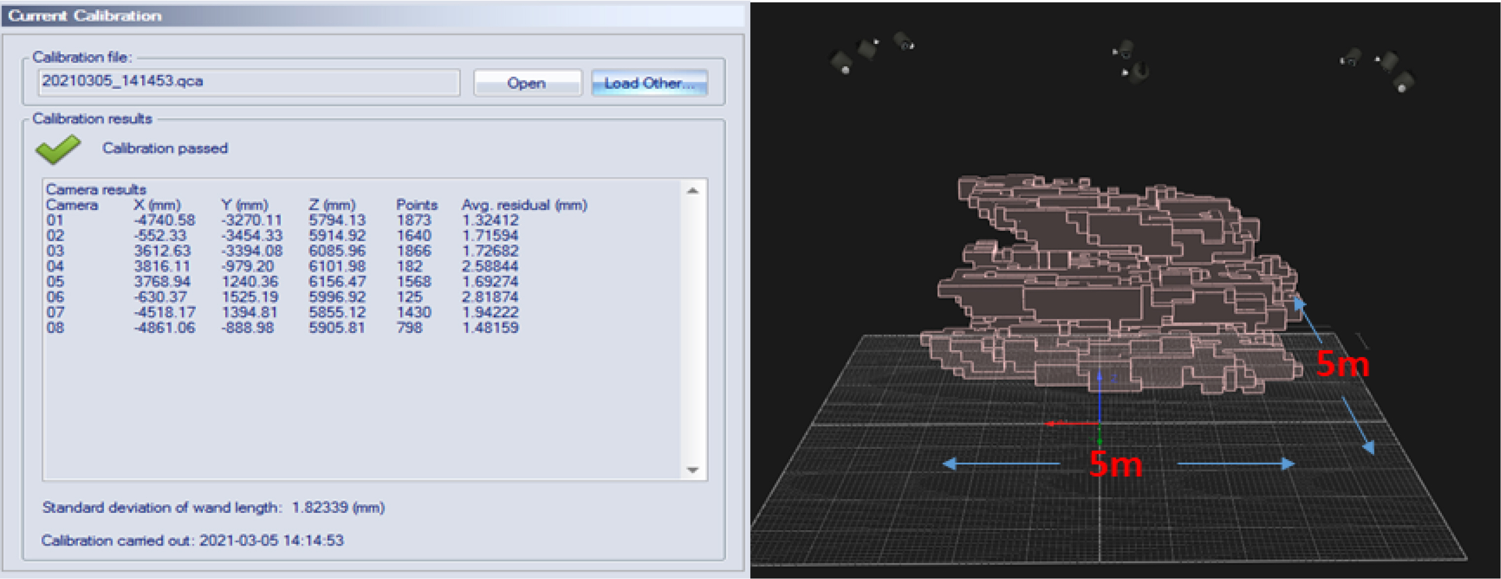
Calibration result of underwater camera measurement area
To evaluate the auto-tracking performance of the towing carriage, the ROV was moved further than the measurement area of the 6-DOF measurement system, and the towing carriage operation was examined.
As shown in Fig. 14, the ROV was subjected to plane motion over a “ㄹ”-shaped path with a width of 10 m and length of 10 m. It was determined that the towing carriage showed good performance of ROV-tracking through the auto-tracking controller.

Result of ROV-“ ㄹ” motion trajectory test for measurement-area expansion model test
To determine the maximum range of measurement area within the DOEB, the ROV was used to indicate the measurable points within the ocean tank as shown in Fig. 15 (on the left). Furthermore, its trajectory test results for the measurement-area expansion model test of the towing carriage are shown in Fig. 3 (on the right). Thus, it was determined that the non-contact 6-DOF motion measurement area was expanded to an area with a width of 15 m and length of 30 m using the auto-tracking control method.

Result for maximum range in DOEB for measurement-area expansion model test
4. Conclusion
An auto-tracking controller was designed for the towing carriage in the DOEB with a width of 50 m, and its characteristics were analyzed through a performance test. It was observed that the auto-tracking control performance of the towing carriage in the DOEB was influenced mainly by the P-gain value and motor driving acceleration. Furthermore, vibration and noise were generated when the excessive driving acceleration was applied on the motor drive of the towing carriage. Based on these observations, this study tested and verified the technology to expand the measurement-range of underwater vehicle motion from the camera measurement area (width of 5 m and length of 5 m) to an area with a width of 15 m and length of 30 m. This includes the movement range of the towing carriage using the carriage’s auto-tracking control methods and non-contact motion measurement system. Thereby, this study addressed the wide-area motion measurement of model ships, the demand for which has been increasing recently.
Further studies would be conducted on a high-speed auto-tracking control method for objects on water to advance the methods for controlling towing carriages in DOEBs.