Numerical Investigation of Motion Response of the Tanker at Varying Vertical Center of Gravities
Article information

Abstract
The vertical center of gravity (VCG) has a significant impact on the roll motion response of a surface ship, particularly oil tankers based on the oil level in the tanker after discharging oil at several stations or positional changes, such as changes in the superstructure and deck structure. This study examined the motion response of the Korea very large crude carrier 2 (KVLCC2) at various VCGs, especially roll motion when the VCG changed. The potential theory in the Ansys AQWA program was used as a numerical simulation method to calculate the motion response. On the other hand, the calculations obtained through potential theory overestimated the roll amplitudes during resonance and lacked precision. Therefore, roll damping is a necessary parameter that accounts for the viscosity effect by performing an experimental roll decay. The roll decay test estimated the roll damping coefficients for various VCGs using Froude’s method. The motion response of the ship in regular waves was evaluated for various VCGs using the estimated roll-damping coefficients. In addition, the reliability of the numerical simulation in motion response was verified with those of the experiment method reported elsewhere. The simulation results showed that the responses of the surge, sway, heave, pitch, and yaw motion were not affected by changing the VCG, but the natural frequency and magnitude of the peak value of the roll motion response varied with the VCG.
1. Introduction
Accurately predicting roll motion is paramount for ensuring the safety and operability of ships and offshore structures in waves. On the other hand, the precise prediction of roll motion remains an ongoing challenge because of the complex nature of estimating roll damping. This challenge is particularly prominent for oil tankers, which undergo positional changes, such as alterations in the superstructure deck structure and discharging oil at several stations. The roll damping coefficient has a pivotal role in ship stability because it is closely associated with the occurrence of various ship stability failure modes identified by the International Maritime Organization (IMO, 2008). Despite the significant advances and the introduction of numerical techniques, roll-damping calculations rely heavily on experimental methods. A common approach involves conducting decay tests to determine the damping coefficients, which are then used as direct inputs in numerical simulations of wave-induced motions.
The periodic variation of the vertical center of gravity (VCG) is often considered an internal factor influencing roll motion. This study examined the motion RAOs (response amplitude operators) of the Korea very large crude carrier 2 (KVLCC2) using potential theory in Ansys AQWA at various VCGs. ITTC (2011) recommended that potential theory can overestimate the roll amplitude in the natural frequency because roll damping is significantly affected by the viscous effect. Therefore, roll damping was estimated using an experimental roll decay from a model test conducted at the CWNU (Changwon National University) model basin. The roll-damping coefficients were then determined based on Froude’s method. The roll decay test for different VCGs showed that roll damping is affected by varying the VCGs. The roll damping obtained from experimental roll decay was used to determine the motion response through potential theory in Ansys AQWA. Incorporating experimental roll decay and numerical simulations calculates the motion response of a ship at various VCGs.
Despite the extensive research on the influence of roll motion, the mathematical models for ship maneuvering have focused primarily on incorporating additional terms for the roll angle by adjusting the VCG values above and below the design draft in the conventional 3-DOF (degrees of freedom) mathematical model. Previous studies utilized computational fluid dynamics (CFD) tools to evaluate the potential impact of changing the metacentric height (GM) values on the maneuvering forces and moments acting on tanker hulls. Park et al. (2018) studied the hydrodynamic forces acting on tanker hulls, considering various VCGs. They indicated that the hydrodynamic forces and moments experienced by the hull are influenced by different conditions and VCGs, highlighting the importance of an accurate estimation of these factors. Fukui et al. (2016) assessed ship maneuverability using a 4-DOF mathematical model incorporating roll motion. The model was used for maneuvering simulations by varying the GM values and ship speeds. The study showed that the proposed 4-DOF mathematical model accurately predicts the effects of GM and ship speed on ship maneuverability. Nguyen et al. (2022) investigated the effects of the loading condition on the hydrodynamic forces acting on the ship to determine the maneuverability. Similarly, Yasukawa et al. (2019) presented a practical maneuvering simulation method considering the roll-coupling effect. They extended an ordinal simulation model, the Maneuvering Modeling Group (MMG), and compared its performance with the variations in GM. This practical approach proved beneficial for the conventional prediction of turning motions by considering the roll-coupling effect.
This study builds on the existing literature that explores the correlation and significance of roll damping. Several notable references, including Froude (1861), Falzarano et al. (2015), and Manderbacka et al. (2019), have provided valuable insights into the importance of roll damping. The literature review encompasses various roll-damping prediction methods and their extensive analysis. For example, Smith (2018) compared different methods for calculating the roll-damping values based on empirical data from roll decay tests. Oliva-Remola et al. (2018) analyzed the influence of different experimental techniques on roll decay tests using a trawler fishing vessel model. Rodríguez et al. (2020) assessed the realistic estimation of roll-damping coefficients in waves using model tests and numerical simulations. Ma et al. (2018) conducted experimental and numerical investigations on ship parametric rolling in regular head waves. Irkal et al. (2017) studied roll damping of a midsection of a ship with a bilge keel, using CFD simulations to determine the effect of the radius of gyration in rolling (kxx) and VCG on roll damping. Collectively, these references contribute to understanding roll-damping phenomena and the associated factors.
2. Roll Decay Test
2.1 Model Test and Set-Up
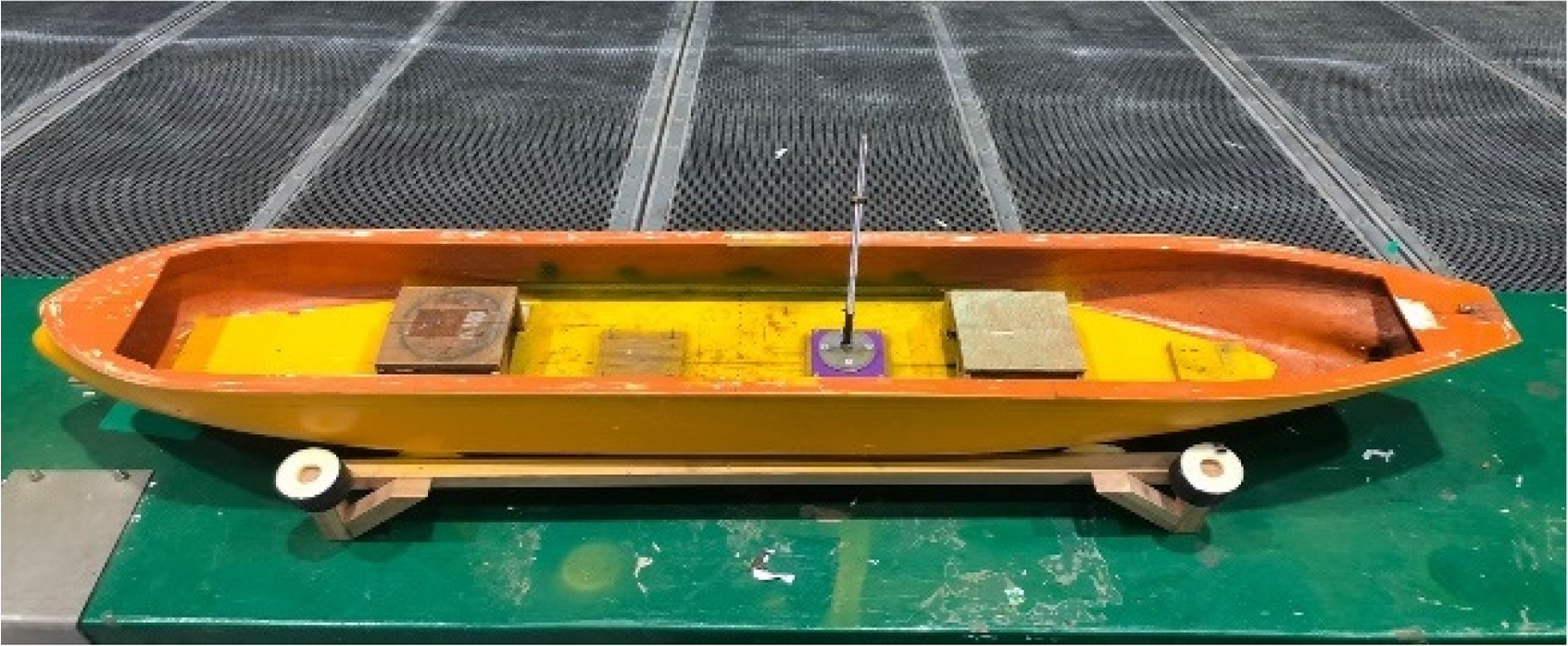
A roll decay test was carried out for the KVLCC2 model scaled at a 1:223 scale ratio. Fig. 1 shows the bare hull of the KVLCC2 model. Table 1 lists the specifications of the full-scale and model-scale of the ship. In the initial phase, the pre-test is crucial for evaluating and acquiring the features of the model ship to be similar to a real ship, which is essential for the subsequent stages of the experiment. In this study, a small 2D tank at CWNU was utilized to determine the draft level of the ship in the ballasting test and GMT in the inclining test. These preliminary steps play a significant role in ensuring data accuracy for the subsequent stages of the study. Table 2 lists the VCG conditions corresponding to GMT, where VCG1 is the design value for the KVLCC2.
KVLCC2 model test

Model test specifications

VCG conditions
A ballasting test was essential to ensure an accurate match between the model and real ships. This test ensured that the mass distribution and draft of the model ship aligned precisely with a real ship. Fig. 2 presents the ballasting of the KVLCC2 model ship. The test was performed using a draft corresponding to the density of seawater. The mass included additional weight and an inclinometer sensor integrated into the ship. On the other hand, owing to the challenges posed by the sensor-attached electrical cables during the ballasting process, it was replaced with an equivalent mass.

Ballasting
After the ballasting test, an inclining test was conducted to verify the transverse metacenter height (GMT). This test involved determining the inclination angle when the mass within the model ship was displaced horizontally while adjusting the height of the weight attached to the stern. The estimation of GMT can be determined by Eq. (1), which involves calculating the heel angle resulting from the change in weight distribution. Fig. 3 defines parameters in the inclining test, where w, W, ly, and ϕ are the moving weight, displacement of the model ship, lateral distance of the moving weight, and heel angle, respectively. Fig. 4 presents the inclining test performance with the moving weight moved to port (Fig. 4(b)) and starboard (Fig. 4(c)). The heel angle (ϕ) was measured using a digital protractor attached to the model ship.

Definition of the parameters used in the inclining test

Inclining test performance
2.2 Experimental Roll Decay
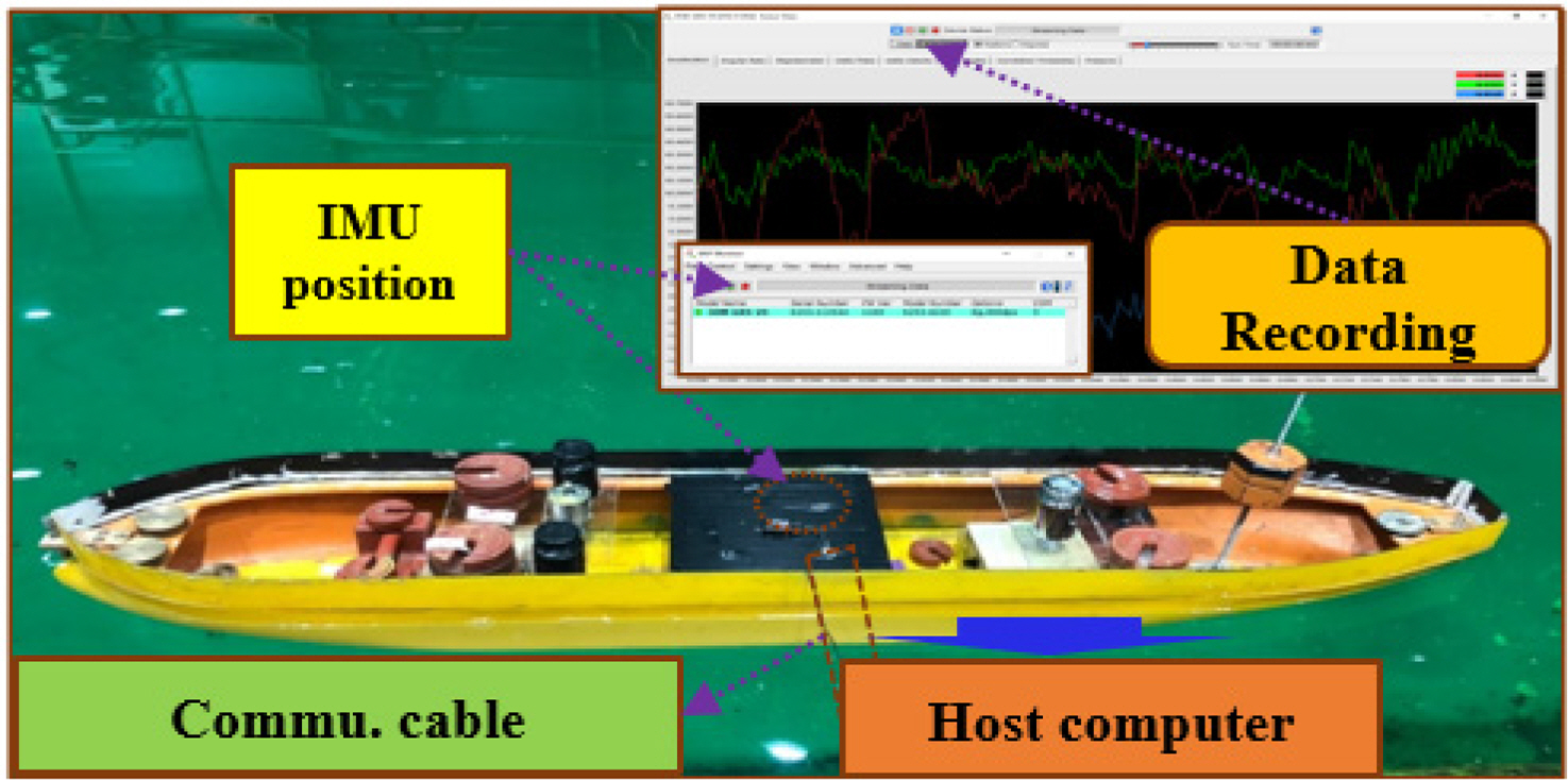
Model tests were conducted in a square tank at CWNU to estimate the roll-damping coefficient of a KVLCC2 model. In this experiment, an inertial measurement unit (IMU) was used to measure the attitude of the model ship during roll motion. The IMU was connected to a host computer through a communication cable, with a continuous power supply for the inertial sensor. The data streaming and recording of the inertial sensor were managed using the multi-isotope process (MIP) monitor. Fig. 5 shows the components and operations of this inertial sensor.
Measurement sensor.
2.3 Roll Decay Results
The IMU system recorded the time series of roll angles for three cases of various VCGs in calm water. The roll decay test performed harmonic roll oscillations with a specific roll period, initiating from the test with a certain initial roll angle. The roll motions were performed with free roll and fixed heave and pitch. Fig. 6 presents the time history results of the roll decay test for different VCGs. The roll period increased as the VCG increased. Subsequently, the measurement roll natural frequencies wn were confirmed to the target periods initially calculated from Eq. (2) for the natural frequency, where m, g, and GMT are the mass, gravity acceleration, and transversal metacentric height, respectively. I44 is the roll mass moment of inertia. a44 is the roll-added mass moment of inertia that was determined to be the simplified 0.25I44 for conventional ships by the United States Naval Academy (USNA). Kianejad et al. (2019) predicted that the non-dimensional roll-added mass moment of inertia was approximately 0.25 for various frequencies at roll angles smaller than 15°. Table 3 lists the measurement roll periods of different VCGs with discrepancies to the target period lower than 1%. Therefore, time histories of the measurement roll decay are used to determine roll damping.

Time histories of the roll decay test for different VCGs

Roll period of different VCGs
2.4 Roll Damping Estimation
The roll damping coefficient can be estimated based on the time series of the roll decay test. As shown in Fig. 6, the time series is described as a 1-DOF equation of motion given by the following equation:
The damping moment can be expressed in terms of the linear and quadratic contribution.
By substituting Eq. (6) into Eq. (4), the rolling equation of motion becomes
Assuming harmonic roll motion and equivalent dissipated energy for both damping representations, an additional relationship between the coefficients p, p1, and p2 can be established as Eq. (8):
Here, the roll amplitude is represented as
Time series histories of the roll decay test for VCG2
This study used the Froude energy approach based on the energy loss balance in each half cycle to analyze the roll decay time records.
The energy dissipated by the damping term is equal to the variation of the potential energy when the kinetic energy at the initial and final positions are zero. The energy balance gives the following assuming the linear plus quadratic damping form and linear restoring moment in the roll decay equation:
For dϕ =ϕ̇dt,
The integration of each term gives
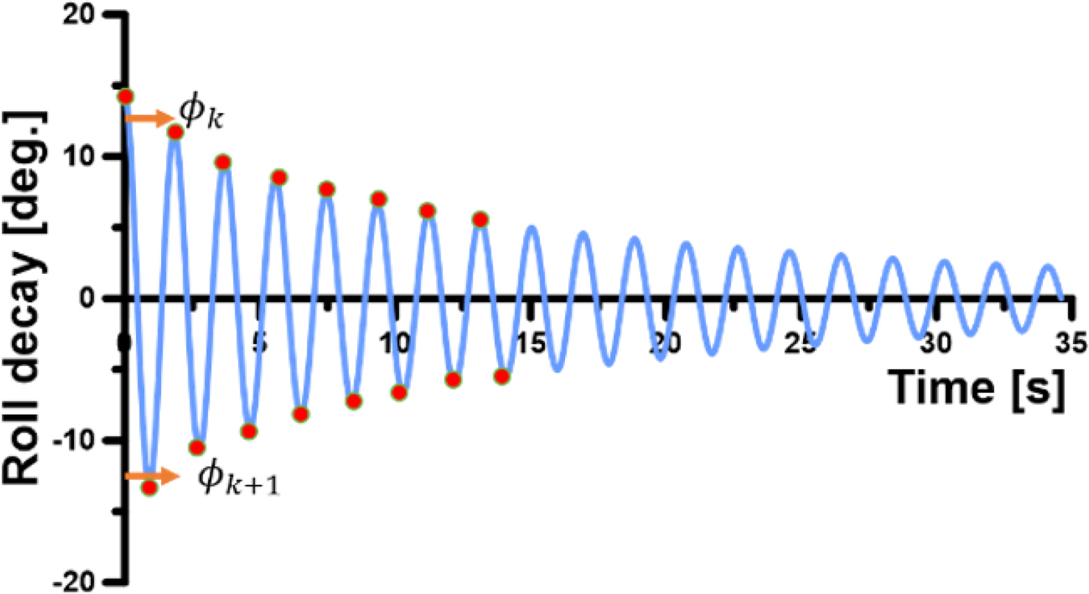
Denoting δϕ =(ϕk − ϕk+1)
Eq. (15) represents a quadratic function for δϕ against ϕa, where p1 and p2 can be obtained using a regression procedure. In this approach, k refers to a positive peak, while the successive k+1 peak refers to a negative one. The non-dimensionalized roll-damping coefficient is expressed as
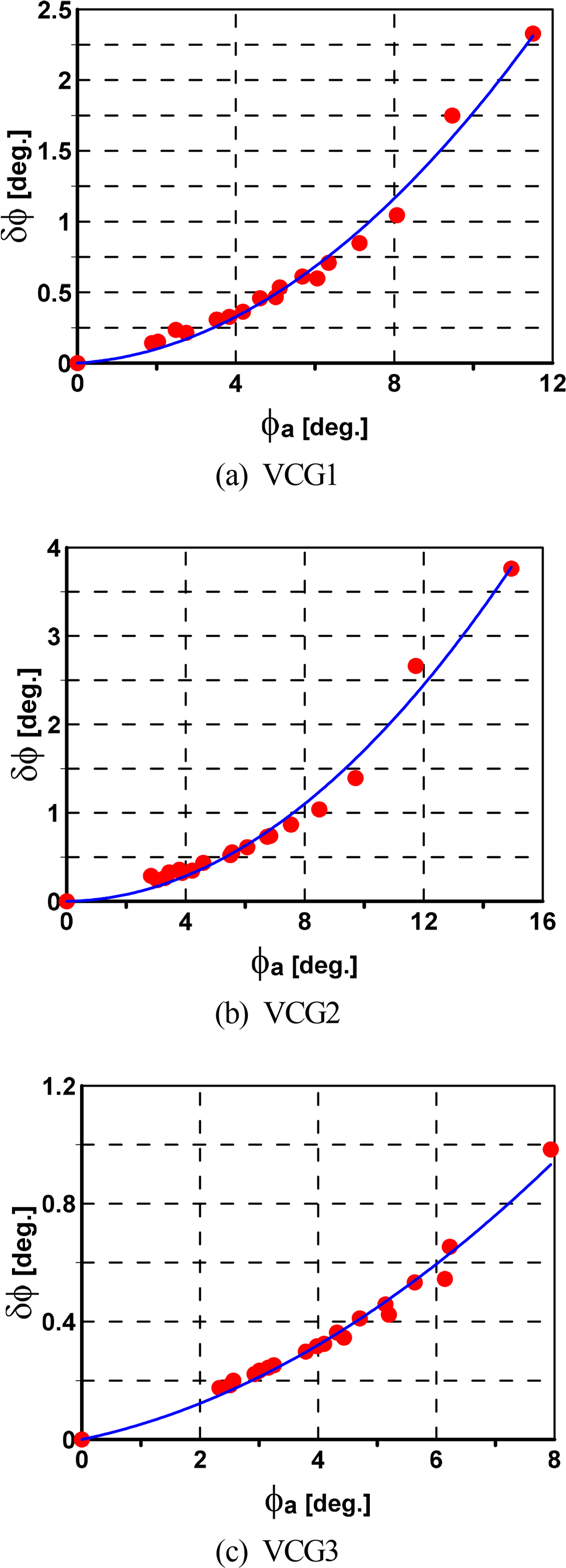
According to the above procedure of the roll damping estimation, Fig. 8 shows the determination of the roll damping coefficient for VCG1, VCG2, and VCG3, respectively. Table 4 lists the damping coefficients for each VCG with the smallest value corresponding to VCG2 and showing incremental increases for VCG1 and VCG2, respectively.
Determination of the roll damping coefficient for different VCGs

Decay damping coefficient.
Applying the estimated damping coefficients in Table 4 to Eq. (3) to simulate the roll decay for verification, Fig. 9 compares the simulation and experiment results of roll decay motion for various VCGs. The simulation results were in good agreement with those of the experiment, highlighting the reliability of the damping coefficients.

Comparison of the simulation and experiment for roll decay
3. Motion response
3.1 3D Panel Method
In this study, the motion response of the ship was calculated using the 3D panel method applied in the potential code of Ansys AQWA. The fluid was assumed to be incompressible, inviscid, and show irrotational flow. The governing equations and boundary conditions of the flow field can be expressed using the velocity potential flow.
The velocity potential can be decomposed into three components: the incident potential (ϕI ), diffraction potential (ϕD ), and radiation potential (ϕR), as expressed in Eq. (21).
The boundary conditions for the diffraction and radiation velocity are given by Eqs. (22) and (23). The potential for an undisturbed incident wave field at a point (x, y, z) in the fluid domain and incident wave potential is estimated in Eq. (24).
P is located in the source on surface S, and G(x, y, z) is the Green function, which describes the flow at (x, y, z). The Green function satisfies the Laplace equation and the boundary condition everywhere except the body surface, and the boundary condition on the surface as
The source strength on the body surface is set by Eq. (27)
3.2 Numerical Simulation
A numerical simulation was conducted for the full-scale ship in Ansys AQWA. The regular waves were generated throughout the simulation for a range of frequencies from 0.1–1.0 rad/s. The simulation was implemented under zero speed and a design speed of 7.97 m/s for a range of wave directions from 0°–180° with 30° intervals. The influence of VCG on the motion RAOs was examined by calculating various VCG values. The roll motion was corrected by applying the roll damping value estimated in the previous section to calculate the roll damping values for the full-scale ship and input them into the additional damping option in the program. The roll damping coefficients, VCGs, and natural roll periods were converted to the full-scale model during simulation. Fig. 10 shows the mesh generation of KVLCC2 for the simulation. Fig. 11 presents the ship motion in regular waves of the simulation.
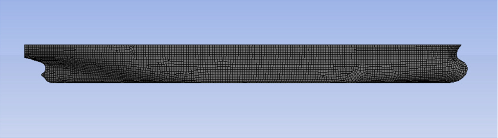
Meshing in Ansys AQWA
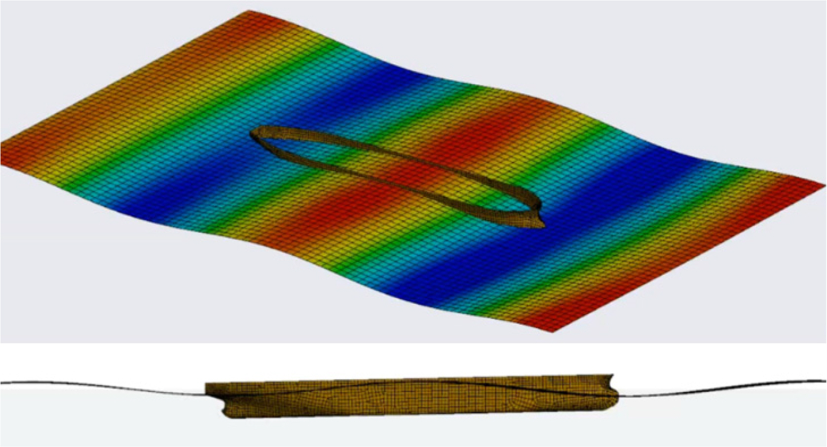
KVLCC2 motion in waves
3.3 Verification
The calculated motion RAOs of the surge, heave, and pitch were compared with the experiment results published by Kim et al. (2017) and Seo et al. (2021) to verify the reliability of the numerical simulation, as shown in Fig. 12. The VCG value for the calculation verification was VCG1 which is the origin value of KVLCC2. The numerical simulations were in good agreement with that of the experiments. Hence, the numerical simulation predicted the motion response of the ship well.

Verification of the numerical simulation at forward speed in head waves
Nevertheless, the numerical simulation using potential theory lacked precision when predicting the roll RAO. Fig. 13 compares the roll RAO w/and w/o additional roll damping (ARD) at a zero speed for various wave directions in the case of VCG1. The roll natural frequency was 0.3 rad/s, corresponding to 21.78 s for both w/and w/o ARD, which is similar to the theory calculation. On the other hand, the peak values at the roll natural frequency of w/o ARD are significantly greater than that of w/ARD. The very high values at the roll natural frequency of w/o ARD are unreasonable. Therefore, additional roll damping must be added to correct the roll motion response.

Comparison of the roll RAO w/and w/o additional roll damping at zero speed
3.3 Motion RAOs
Fig. 14 presents the 6-DOF motions for various VCGs at a forward speed and a wave direction of 120°, where 6-DOF motions are observed clearly, to clarify the effect of VCG on the motion RAOs. The motion responses, except for the roll motion, appear identical across various VCG values. Hence, VCG affects only the roll motion of the ship. Therefore, a detailed analysis of the roll RAO was conducted, as shown in Figs. 15 and 16, considering various VCGs, wave directions, and speed conditions. The peak values of roll RAO for various VCGs occurred at different frequencies; specifically, the lower VCG of VCG2 was earlier than the higher VCGs of VCG1 and VCG3. By contrast, the roll RAO amplitude of VCG3 was the smallest, and it increased incrementally with VCG1 and VCG2 because of the magnitude of the estimated damping coefficient in the previous section, in which the damping coefficient of VCG was the smallest. Moreover, the roll RAO amplitude is observed to be increased as the wave direction becomes 90°. Regarding the speed effect, the amplitudes of roll RAO at forward speed were higher than those of zero speed at wave directions of 150° and 120°. On the other hand, these amplitudes were similar at a wave direction of 90° under the forward speed and zero speed conditions.
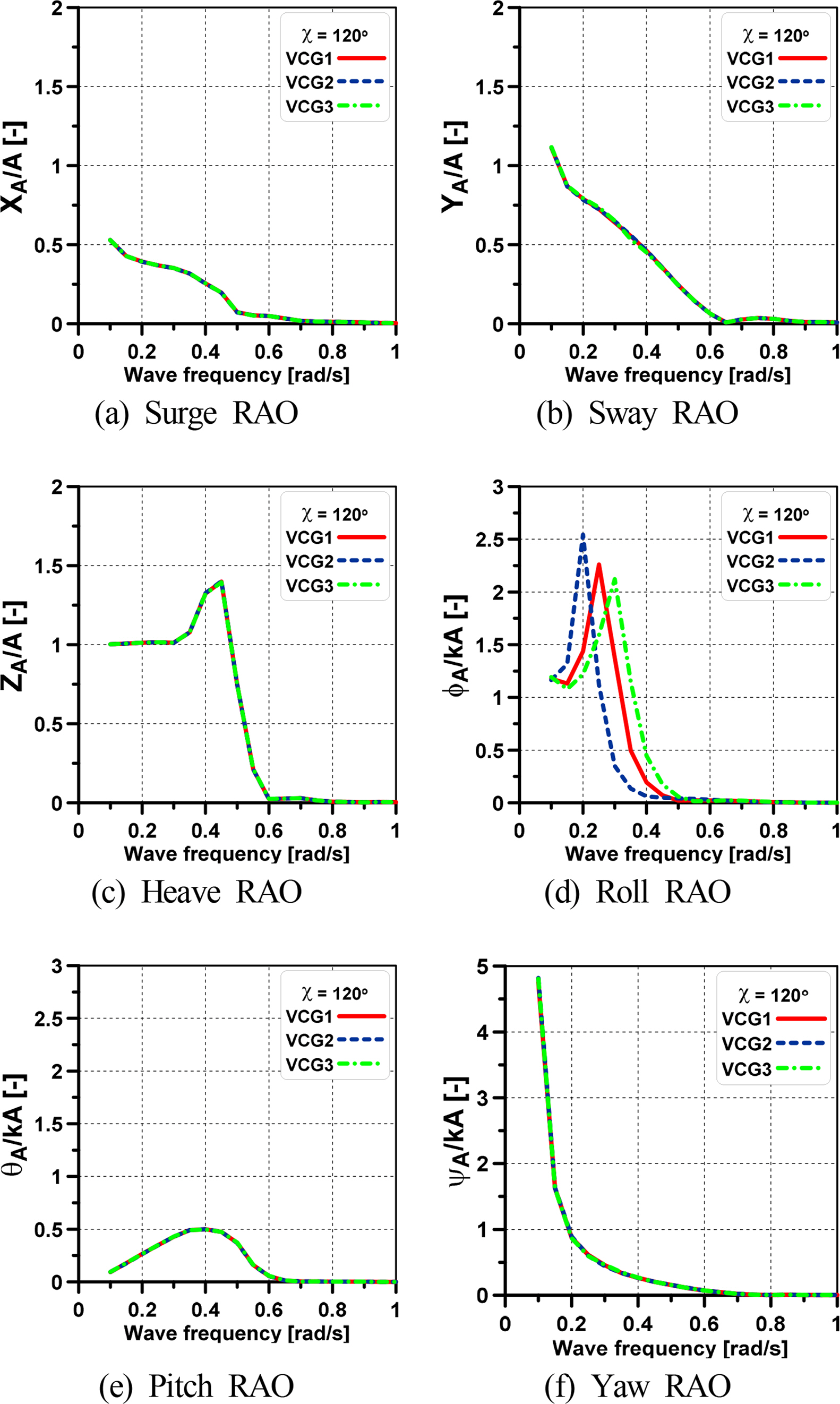
Motion RAOs of the ship for various VCGs at a wave direction of 120° and forward speed

Roll RAO for various VCGs at zero speed
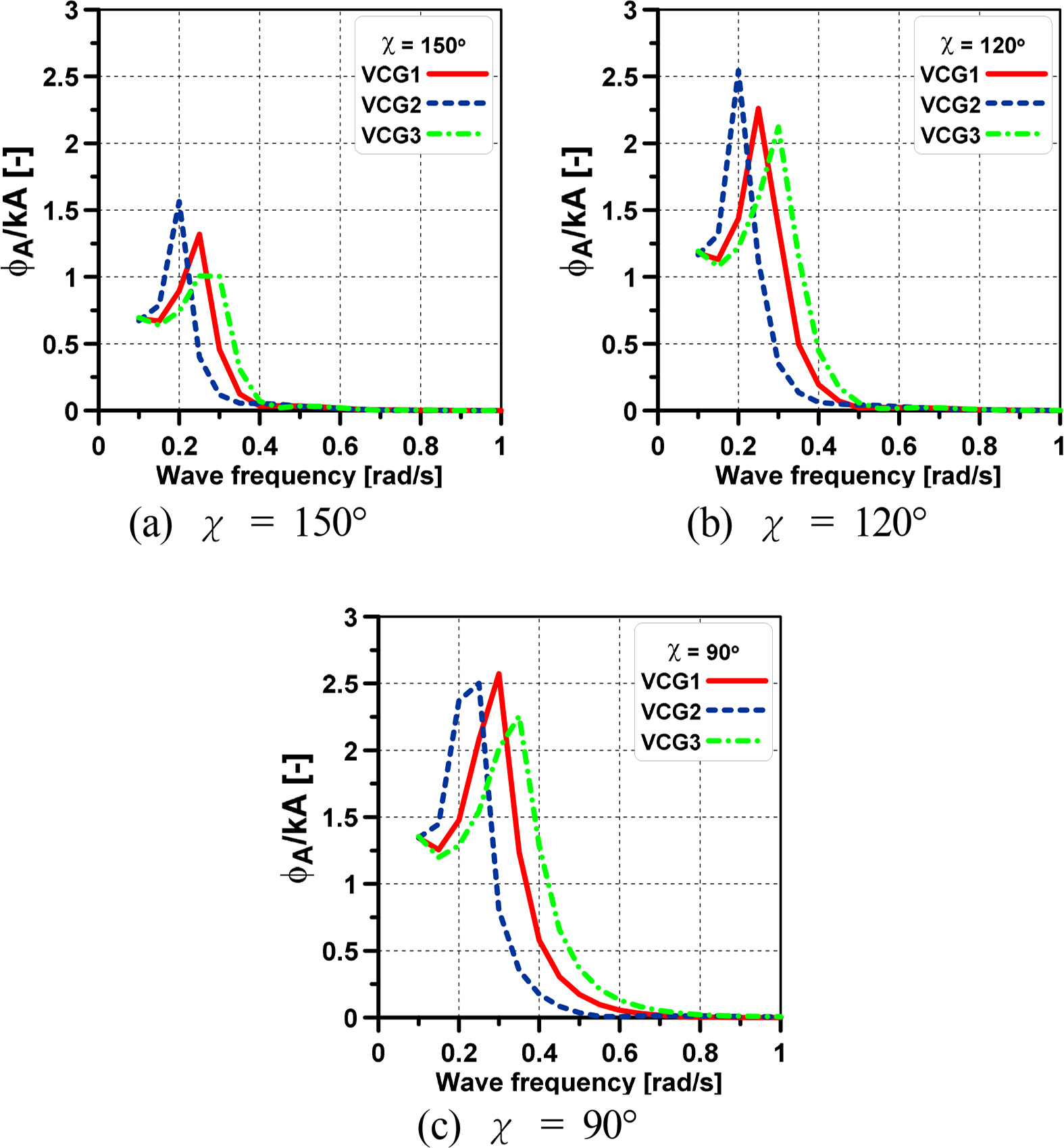
Roll RAO for various VCGs at forward speed
6. Conclusions
This study examined the significant impact of the VCG on the motion response of the surface ship, particularly on the roll motion response. The KVLCC2 model, which is representative of tankers, and applied potential theory in Ansys AQWA were used to analyze motion responses. A notable limitation in potential theory was identified, which tended to overestimate the roll amplitude during resonance and lacked precision. This limitation was overcome by introducing an essential parameter, roll damping, which was calculated through an experimental roll decay test to account for viscosity effects. The roll damping coefficient was estimated based on the time series of roll decay using the Froude method for various VCGs. The lower VCG values resulted in smaller roll-damping coefficients, with incremental increases observed as the VCG values increased. Moreover, the reliability of these damping coefficients was demonstrated by comparing the simulation of 1-DOF for the roll equation of motion to the experimental roll decay time series for various VCGs.
The motion response of the ship determined using potential theory was verified by comparing the motion response with the experimental method. In addition, simulation results of motion responses at various VCGs indicated that VCGs did not affect the surge, sway, heave, pitch, and yaw motion, but the roll motion response varied with VCG changes. In particular, the peak value of roll motion for various VCGs occurred at different frequencies, with a lower VCG value corresponding to an earlier frequency for the peak value than the higher VCG values. In contrast, the lower VCG value exhibited a higher peak value of roll RAO, which decreased with higher VCG values. Further research in this area could lead to more effective strategies to minimize rolling motion and enhance the stability of the maneuvring and seakeeping test, contributing to the safety and efficiency of maritime transport.
Notes
Hyeon Kyu Yoon serves as a journal publication committee member of the Journal of Ocean Engineering and Technology but played no role in the decision to publish this article. No potential conflict of interest relevant to this article was reported.
This research was supported by Changwon National University in 2023–2024.