
1. Introduction
Owing to the continuing increase in global energy demand, the consumption of fossil fuels, a traditional non-renewable energy resource, is also showing a steady increase. Fossil fuels are suitable as a major energy source because of their storage practicality and capability of generating a large amount of energy; however, they are also the source of growing environmental concerns owing to the excessive emission of greenhouse gases such as carbon dioxide, NOx, and SOx. Considering their limited reserves, fossil fuels are expected to deplete. In preparation, sustainable and eco-friendly energy has been attracting attention. Among them, the development of marine energy and technologies for practical use and commercialization of the energy is a challenge that must be prioritized. Among the different types of marine energy, energy generated from ocean waves is an eco-friendly and sustainable energy source with a near-infinite potential for power generation (Roh et al., 2020). In addition, wave energy is the energy source with the highest energy density per unit area among marine energy sources (Kim et al., 2014). However, because wave energy is significantly affected by the unpredictable irregularities and seasonal variability of ocean waves, the development of advanced technology is required to ensure stable energy extraction. Power generation methods for extracting wave energy can be divided into wave-activated bodies, oscillating water columns (OWCs), and overtopping devices (Seo et al., 2020).
With OWC wave energy converters (WECs), the incident wave enters a chamber, a closed space in the oscillating water column, to change the elevation, which leads to a change in the volume of the air inside the chamber. In this manner, the wave energy is first converted into airflow energy. The generated airflow rotates the air turbine installed in the nozzle at the top of the chamber; this process involves the secondary conversion of the airflow energy into mechanical rotation energy to generate electricity (Kim et al., 2007). OWC WECs have a highly reliable power generation method and ease of maintenance, as the power take-off (PTO) is located above the water surface, drawing active research interest (Boccotti, 2003; Elhanaf et al., 2016). Numerous experimental studies have been conducted on OWC development (Hong et al., 2006; Kim et al., 2012), as well as numerical analysis studies using computational fluid dynamics (CFD) (Elhanaf, 2017; Simonetti et al., 2018; Vyzikas et al., 2017). In addition, a comparative analysis has reported on modeling an open chamber without an air turbine effect and orifice chamber modeling that considers the turbine effect (Koo et al., 2010).
In addition, by installing OWC WECs integrated with the bottom-fixed breakwater along the coast (Park et al., 2018), more generator modules can be installed, which leads to an excellent energy extraction effect and advantage in securing the installation site. However, for the breakwater-linked OWC WECs, the skirt of the chamber is inclined because of the side inclination of the breakwater (approximately 30 degrees). Considering the inclined structure, there is a high possibility of fluid viscous dampening the incident wave at the end of the chamber skirt. Therefore, to increase the energy extraction efficiency of the OWC chamber, incident wave energy must be transferred into the chamber while minimizing the viscous damping of the incident wave generated at the end of the skirt (Wang and Ning, 2020).
In this study, numerical analysis and experiments were conducted on the viscous damping effect according to the shape of the OWC chamber skirt of a bottom-fixed breakwater-linked OWC WEC in coastal regions, and the two sets of the obtained results were compared. Experiments on a breakwater-linked OWC WECs model were performed using a two-dimensional mini wave tank. As the typical inclination angle of the bottom-fixed breakwater installed in the domestic coastal region is 33.7┬░, the inclination angle for the experimental model of the breakwater-linked OWC was fixed at 33.7┬░. For the shape of the chamber skirt, two different shapesŌĆöpointed and roundedŌĆöwere assumed for a comparative evaluation of the wave elevations in the chamber accordingly; the fluid viscous damping effect of the incident wave was comparatively analyzed for the two shapes. In addition, for the same experimental model, the CFD program (Star CCM+) was used to simulate the displacement of water surface with regular waves of different periods, and the results were compared with the experimental results to verify the validity of the computation. Through this study, the fluid viscous damping effect was analyzed with different OWC chamber skirt shapes, and the feasibility of a structural design capable of achieving maximum energy extraction while minimizing incident wave energy loss is discussed.
2. Numerical Model
2.1 CFD Analysis
A numerical analysis was performed using Star-CCM+ (Ver. 15.06), a commercial software based on modeling viscous fluid. The governing equations for the fluid domain are a continuity equation and the RANS (Reynolds-averaged NavierŌĆōStokes) equation. An implicit unsteady condition is applied for time domain analysis. To simulate the multiphase reactions of continuous flows, the physical properties of two fluid phasesŌĆöwater and airŌĆöwere defined based on the Eulerian multiphase method (EMP). The EMP solves the transport equations for mass, momentum, and energy of each phase based on the assumption that all phases share the same pressure field. The interface was defined as a free surface, and the volume of fluid (VOF) method was used to represent the displacement of the free surface. A segregated flow solver was set to model the flow, and a realizable kŌłÆŌłŖ turbulence model was applied for turbulence analysis. A linear regular wave was used as the incident waves. Table 1 lists all CFD simulation setting.
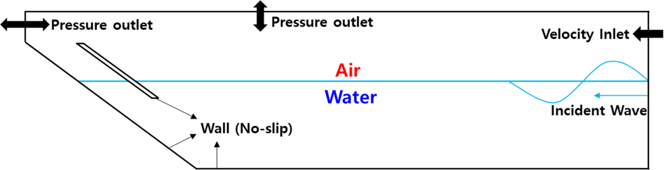
Fig. 1 presents a schematic of the computational domain and boundary conditions for a numerical model of the breakwater-linked inclined OWC. The impermeable rigid boundary conditions were applied using the wall boundary conditions for the rear wall of the OWC, seabed, skirt, and side wall (inner wall in the figure) in the 3D computational domain. To make conditions similar to the experimental conditions, a no-slip condition was applied to the fluid particles on the wall. For the outer surface of the computational domain (the outer surface in the figure), the boundary condition of an x-axis symmetric plane was applied to reduce the total number of nodes and the resulting computation time. To generate an incident wave from the wave maker on the right side of the computational domain, a velocity inlet boundary condition was set, and a forcing zone that can forcefully maintain the condition was applied at 2 m. By applying the forcing zone, the computational domain can be reduced by another solution (in this case, the velocity field of the incident wave) on the domain instead of the solution of the discretized Navier-stokes equation.
In the experiment with a wave tank, the energy component of the evanescent mode decreases exponentially per the horizontal length moving away from the wave maker, and a wave with an energy component approximately 25% larger than the predicted incident wave height is generated near the wave maker. This condition is the evanescent mode of the reflected wave, and it is affected by the standing wave of the reflected wave generated by the motion of the wave maker (Kwon et al., 2019). To prevent this phenomenon in the simulation, a forcing zone was set near the piston-type wave maker. To define the interface of the nozzle outlet where the air flows out, a pressure outlet boundary condition was applied to the upper surface of the computational domain and upper surface of the rear wall of the OWC, while the static pressure condition of the external pressure was set as the pressure boundary conditions.
For the mesh spacing in the computational domain, 1/100 of the wavelength of the incident wave was applied in the direction of the wave propagation, and 1/20 of the wave height of the incident wave was applied in the direction of the wave height. A trimmer mesh suitable for modeling the wave tank was applied. To represent the wave displacement inside the OWC chamber, the mesh size was further subdivided into 1/32 in the wave propagation (horizontal) direction and 1/8 in the wave height (vertical) direction to increase the accuracy of wave elevation measurements inside the OWC chamber. The total number of meshes used in the simulation was set to 3 million. In the experiment with a two-dimensional mini wave tank, as it is difficult for the hydrodynamic characteristics of the small-scale turbine model to follow FroudeŌĆÖs similarity law, the open chamber and orifice chamber conditions were applied for simulation, instead of a precise simulation of a turbine model. Comparing the results of the two chamber conditions, the effect of applying PTO was analyzed. In addition, the energy conversion performance of the incident wave energy was examined, and the phenomenon of amplification of the incident wave elevation after entering the OWC chamber was discussed. The length (X) of the computational domain was set to 5.62 m, as in the wave tank used in the experiment. The length of the actual tank is 6 m, but the piston-type wave maker was installed at a slight distance from the end wall of the tank, and this small separation was considered when setting the computational domain. The depth and width of the mini wave tank were 0.32 and 0.3 m, respectively. In the computational domain, a boundary condition of a symmetric x-axis (wave propagation direction) was set, and the width (Y) was set to 0.15 m. In addition, the height of the computational domain, including the water depth of 32 cm, was set to 50 cm, with the computation performed in three dimensions.
3. Experiment Equipment and Settings
3.1 Two-dimensional Mini Wave Tank
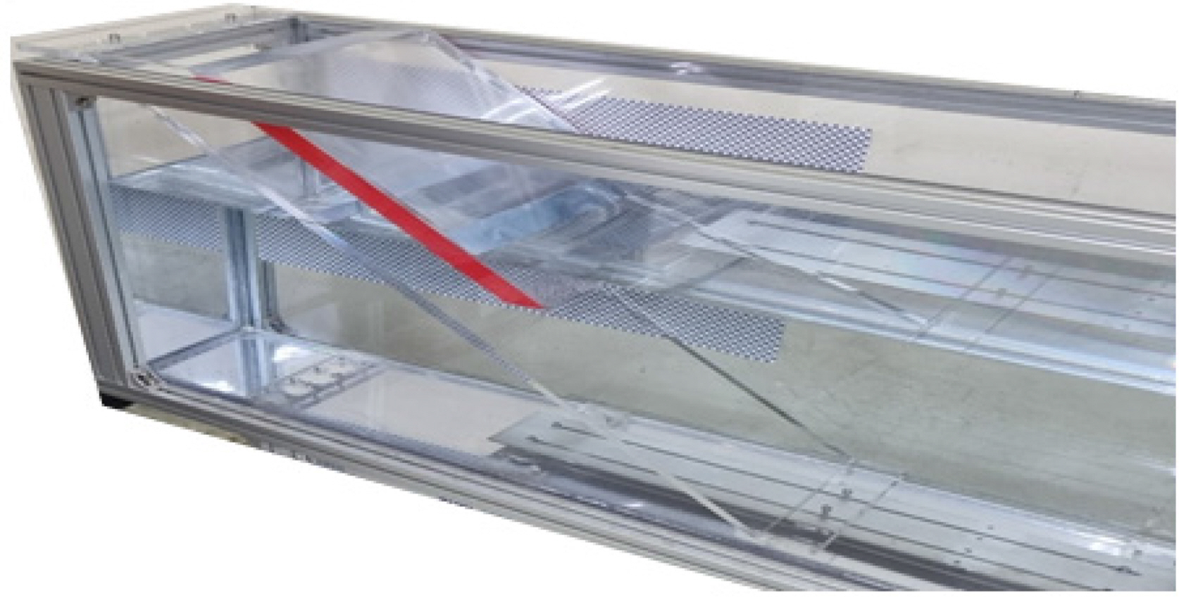
In this study, a two-dimensional mini wave tank of Inha University was used. The mini wave tank was 6 m in length, 0.5 m in height, and 0.3 m in width, and the bottom and sides were transparent acrylic such that waves were observable from any direction (Fig. 2). A piston-type wave maker was used. The generated waves reflect from the OWC installed on the end wall in the propagation direction and re-enter the wave maker. Therefore, the wave before the reflected wave is re-reflected from the wave maker and reaches the OWC was used for the analysis of the results. This setup excludes the influence of the reflected wave when generating the incident wave and uses only the target incident wave. The incident wave period was in the range of 0.8 to 1.2 s, with waves made at intervals of 0.1 s, and the range of wavelength was 0.98 to 1.86 m. The wave height of the incident wave was fixed at 2 cm to generate a uniform and regular wave height. For the comparative evaluation of the generated incident wave using numerical analysis and experiments, the data sampling rate was 20 per second (20 Hz). Table 2 outlines the experimental conditions for each wave period and wavelength.
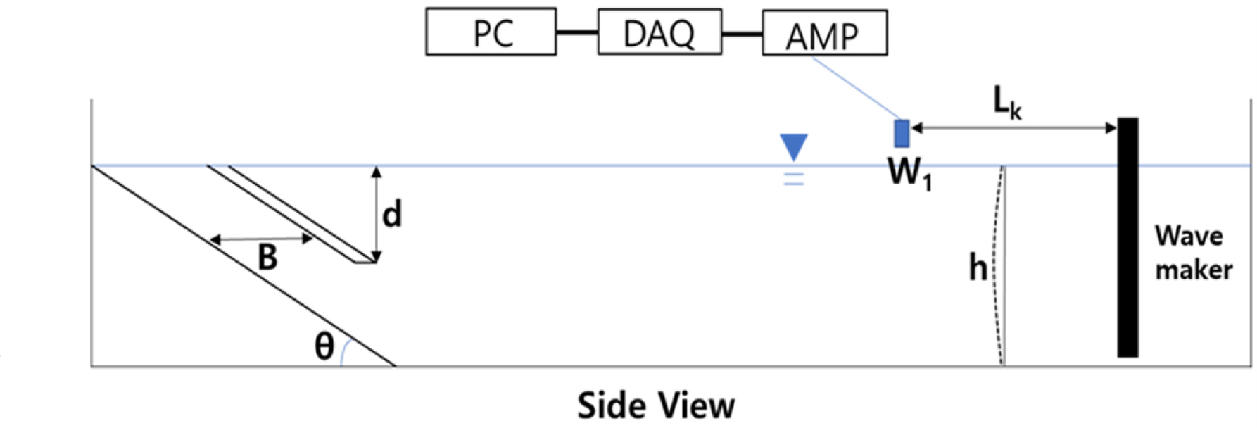
Fig. 3 is a schematic of the experimental setting of the two-dimensional mini wave tank for an inclined OWC chamber with an open chamber. B denotes the gap (width) of the OWC chamber, d the draft of the skirt, and ╬Ė the inclination angle between the inclined OWC chamber and seabed. In addition, h is the water depth, W1 is the wave gauge, and Lk is the distance from the wave maker to the wave gauge. The thickness of the skirt was fixed to 2 cm to maintain the structural strength of the OWC experimental model without affecting the wave elevation in the chamber. An ultrasonic wave gauge was used to measure the incident wave height, and the distance (Lk) between the wave maker and wave gauge (W1) was set to 2 m to avoid the evanescent mode generated by the wave maker. The signal measured by the ultrasonic wave gauge was amplified using an amplifier (AMP) and sent to a data acquisition device (DAQ), and the measurement data was then stored in a computer for analysis.
3.2 Ultrasonic Wave Gauge
To accurately measure the incident wave height, an ultrasonic wave gauge (TSPC-30S2, Senix) was used (Fig. 4). Table 3 presents the specifications of the wave gauge. The ultrasonic wave gauge meaures the wave height by emitting ultrasonic waves in the vertical direction and measuring the time reflected from the sea surface with a transducer. As ultrasonic waves propagate slower in air than in water and are affected by temperature changes, a built-in temperature compensation circuit was provided in the wave gauge.
3.3 Inclined OWC Model
The inclined OWC model used in the experiment was designed with a CAD program and made using acrylic material. In Fig. 2, a two-dimensional mini wave tank installed with the top of the OWC chamber open (open chamber) is presented, and the OWC skirt is marked by red taping. As measuring the wave elevation inside the inclined OWC chamber is difficult with an ultrasonic wave gauge that can measure only the vertical direction, a graph paper was attached to the wall of the two-dimensional mini wave tank, experimental images were taken frame by frame, and the wave height inside the OWC chamber was measured at steady state.
When the incident wave enters the OWC chamber, a vortex can be generated owing to the skirt shape of the chamber inlet, causing incident wave energy loss because of fluid viscosity. For further investigation of this phenomenon, skirt models of a pointed and rounded skirt were produced (Fig. 5). The rounded-skirt was made in a semicircular shape with a radius of 1.25 cm to minimize the effect of fluid viscosity lower than that of the pointed-skirt. In this experiment, to exclude variables other than the shape of the skirt, the draft (d) of the skirt was fixed at 5 cm.
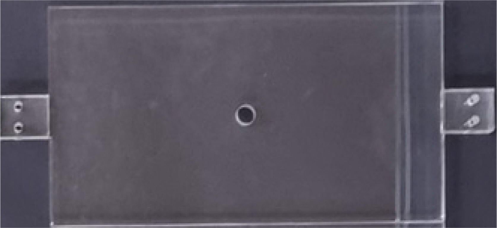
The PTO extraction coefficient for acquiring energy from the OWC chamber, expressed as a ratio related to the volume of the OWC chamber and orifice area, was set to a linear pneumatic damping coefficient (Cdm), based on the assumption that the air in the OWC chamber is not compressed and can be smoothly discharged through a relatively large orifice. Fig. 6 is the upper plate of the chamber used in the experiment, and the diameter of the orifice is 1.4 cm. For comparison with the experiment results, the pneumatic damping coefficient was set to 200, corresponding to the value when the volume (per unit width) of the OWC chamber is 16 times the orifice area.
4. Results of Numerical Analysis and Experiments
4.1 Comparison of Incident Wave Elevations
In this study, numerical analysis was conducted under various wave conditions to examine the hydrodynamic characteristics of the inclined OWC chamber. If the generation and propagation of the incident wave are not performed accurately, the flow inside the OWC chamber cannot be considered reliable. Therefore, checking that the wave is properly generated at the incident wave boundary of the numerical wave tank and propagated without dissipation to the OWC chamber is important. In addition, the elevation of the incident wave was measured using a wave gauge, and whether a regular wave was properly generated and propagated with the same period as the incident wave period was evaluated.
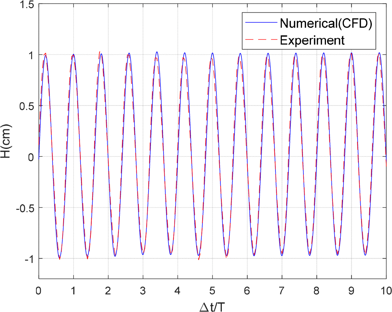
In Fig. 7, the time-series data of the incident wave generated from the experiment and CFD analysis were compared. The two waves show good agreement. Here, the x-axis is made dimensionless by dividing the time interval by the incident wave period, and the y-axis represents the measured incident wave elevation. The point at which the wave elevation was measured is 2 m away from the incident wave boundary, and wave-making was confirmed to have been performed properly by generating regular waves as the incident wave.
4.2 CFD analysis
The real seas applied in the numerical simulation of this study were set as Ganjeolgot Cape near Ulsan, an area with a small tidal range. This location was chosen based on the smooth operating conditions of the breakwater-linked inclined OWC WEC. The experiments and numerical analysis were performed by reducing the water depth, height, and period of the real seas according to FroudeŌĆÖs similarity law. Considering the specifications of the experiment wave tank, the reduction scale was 1/40 compared to that of the real seas. Table 4 presents the specifications of the 1/40 scale-inclined OWC model used in the numerical analysis and two-dimensional mini wave tank experiment. The depth of the real seas was 12.8 m, and the depth for the 1/40 scale model was 0.32 m. Considering parametric analysis and wave tank specifications, the gap (width) of the OWC chamber was set to 0.06 m, the draft of the skirt to 0.05 m, and the thickness of the skirt to 0.02 m. In addition, the angle between the rear wall of the skirt and tank bottom was set to 33.7┬░, similar to the inclination of a typical bottom-mounded breakwater on the coast of the Korean Peninsula. The length of the numerical wave tank was set the same as the experimental condition with the wave tank. Table 5 shows the wave conditions for the numerical analysis and experiment of the inclined OWC chamber. Five conditions (cases) were set by increasing the period of the incident wave of the model condition at regular intervals (0.1 s). Previous studies confirmed that the displacement of the water surface inside the OWC chamber is greatly affected by the draft (d) of the skirt and gap (B) of the OWC chamber (Koo et al., 2012).
Table 6 compares the wave elevation inside the OWC chamber for different incident wave cases under the open chamber condition for the pointed- and rounded-skirt conditions. Hi represents the incident wave height, Hch the wave height within the OWC chamber, and RHP and RHR represent the ratio of the relative wave height in the chamber against the incident wave height under the pointed- and rounded-skirt conditions, respectively. The difference ratio for the two conditions (difference ratio, DR, %) can be represented as (RHR ŌłÆ RHP )/RHP ├Ś100.
For the ratio of relative wave height in the chamber to the incident wave height (RHP and RHR), the maximum values measured at the wave period of 1.1 s (model condition) was approximately 4.6, regardless of the skirt shape. As the incident wave period nears 1.1 s, the water surface displacement in the chamber increases, and the displacement decreases for the incident wave period conditions larger than 1.1 s. In addition, a relative wave height in the rounded-skirt condition was measured larger than the pointed-skirt condition for all incident wave periods, and in Case 2 (wave period of 0.9 s), the DR (%) was approximately 47%. The result indicates that the fluid viscous damping generated when the incident wave enters the chamber is significantly smaller in the rounded-skirt condition than in the pointed-skirt condition. In other words, for the rounded-skirt shape, the incident wave energy consumption caused by the fluid viscous damping can be considered minimized, resulting in more wave energy flowing into the chamber.
In addition, through the DR (%) of the water surface displacement in the chamber, when the incident wave period is smaller than the resonance period (0.8ŌĆō1.0 s), the water surface displacement in the rounded-skirt was at least 36% larger than that in the pointed-skirt condition. However, in a period larger than the resonance period (1.1 s or more), the displacement is relatively small, indicating that, under long-wave period conditions, incident wave energy can easily enter the chamber regardless of the shape of the skirt end, and the effect of viscous damping is relatively small. Therefore, to increase the energy extraction efficiency of the breakwater-linked OWC, designing a skirt shape that minimizes viscous damping under the operating conditions with a wave period smaller than the resonance period is necessary.
Table 7 shows the calculation result of the wave elevation inside the OWC chamber according to the skirt shape with an orifice in the inclined OWC. The orifice functions as an energy conversion device that performs the first conversion of the incident wave energy entering the OWC chamber into pneumatic energy. As the incident wave passes through the skirt and a wave crest is formed in the OWC chamber, the airflow in the OWC chamber is discharged through the orifice (nozzle). The discharged airflow energy is extracted from the incident wave energy in the chamber, and the wave elevation inside the OWC chamber decreases by as much as the extracted energy. In addition, as a wave trough is formed in the OWC chamber, the airflow enters the chamber through the nozzle, and the decrement of the wave elevation inside the OWC chamber is reduced by the incoming airflow energy. Thus, a type of damping acts on the displacement (rise and fall) of the water surface inside the OWC chamber. In addition, the water surface in the orifice chamber is significantly higher in the rounded-skirt condition than in the pointed-skirt condition, indicating that, under the rounded-skirt condition, the amount of residual wave energy in the chamber is considerably large even after subtracting the pneumatic energy extracted by the orifice. Moreover, the generated energy loss owing to fluid viscosity in the skirt corresponds to the difference between the rounded- and pointed-skirt results.
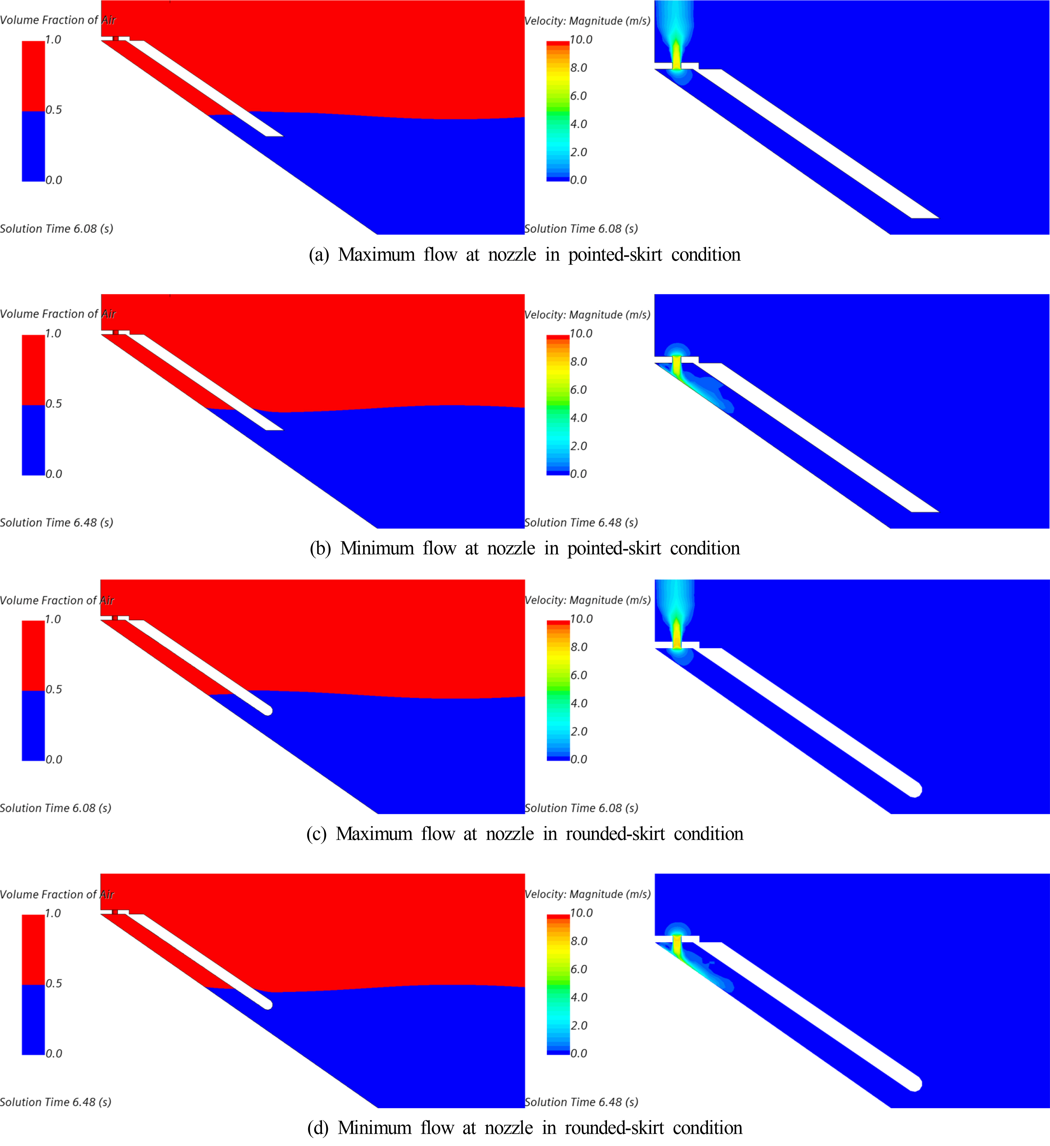
Fig. 8 shows a comparison between the maximum and minimum flow rates inside the OWC chamber with different skirt shapes with an orifice. The wave period was 0.8 s, and the wave height was 0.02 cm. The figure on the left shows the wave elevation, and the figure on the right shows the air flow rate in the orifice. In Figs. 8(a) and 8(c) the water surface displacement inside the OWC chamber indicates the moment when the elevation rose from the minimum level to the average level; at this time, the force to move upward is the largest, maximizing the air flow rate discharged through the orifice inside the OWC chamber. Conversely, in Figs. 8(b) and 8(d) the water surface displacement inside the chamber indicates the moment when the elevation is reduced from the maximum level to the average level; at this time, the force to move downward is the largest, and the airflow rate absorbed by the orifice becomes the maximum.
Table 8 shows the comparison of the water surface displacement in the open and orifice chambers with different skirt shapes. As the incident wave period increases, the difference in wave elevation in the orifice chamber increases compared with the open chamber, and the maximum difference is shown at a wave period of 1.1 s, which is the chamber resonance period. In particular, in the pointed-skirt condition, a wave elevation difference of up to 55.4% occurs depending on the presence or absence of an orifice (wave period of 1.1 s). Consequently, this difference in wave elevation is the effect of the pneumatic energy extraction through the orifice and the effect of the additional energy attenuation caused by the orifice condition. In other words, as wave energy is converted into pneumatic energy in the orifice condition, the wave elevation in the chamber is lowered and the difference is extracted as energy; for some of the energy, additional energy attenuation occurs during energy conversion.
Meanwhile, under the rounded-skirt condition, the ratio (DR) of the wave elevation difference between the open and orifice chambers is smaller than that in the pointed-skirt condition. Although a relatively large amount of wave energy flows into the chamber, and the influx of the energy is converted into pneumatic energy, the residual wave energy is also considerably large, resulting in a small wave elevation difference (ratio). In other words, in the rounded-skirt condition, the wave elevation inside the chamber being significantly higher than in the pointed-skirt condition indicates that the residual wave energy remaining after conversion to pneumatic energy is large. If the size of the orifice is optimized, it maximizes the energy extracted and minimizes the wave elevation in the chamber. Moreover, at a wave period of 0.8 s under the rounded-skirt condition, the water surface displacement is larger in the orifice chamber condition than in the open chamber condition, signifying that, under the rounded-skirt condition of a specific wave period, although a large amount of incident wave energy is introduced and some energy is extracted owing to the orifice chamber, a large amount of residual energy remains. However, more detailed analyses such as those involving changes in the pneumatic pressure inside the chamber and particle kinetics are required to identify the exact cause of the result. In conclusion, this study shows that in the rounded-skirt condition, maximizing energy extraction is possible through orifice size optimization while minimizing energy attenuation.
4.3 Comparison of Experimental and CFD Simulation Results
In Fig. 9(a), the displacement of the water surface inside the chamber with different skirt shapes in the open chamber condition was compared with the numerical analysis and experiment results; overall, the results show a good agreement. The change in wave elevation according to the skirt shape is large for wave periods of 0.8ŌĆō1.0 sŌĆöa range of relatively short wavesŌĆöpossibly because of the large decrease in viscous energy under the pointed-skirt condition as previously discussed. However, the difference in surface displacement is insignificant at the resonance period (1.1 s) and period conditions longer than the resonance period, possibly because the shape of the skirt has a minimal effect on the incident wave entering the OWC chamber owing to the characteristics of the long waves.
Comparing the numerical analysis and experimental results according to the skirt shape of an OWC with an orifice installed (Fig. 9(b)), the results show a generally good agreement. Compared to the result of the open chamber condition in Fig. 9(a), a clear resonance period cannot be confirmed, and the wave elevation inside the chamber can be seen to increase with the wave period. The difference between the pointed- and rounded-skirt results in the orifice chamber condition is because of the fluid viscous damping that occurs in the skirt. Comparing the results through the figures, the viscous damping under the pointed-skirt condition is seen to be considerably large for all values of the incident wave period. In addition, as the incident wave period increases, the energy loss owed to fluid viscosity is seen to gradually increase.
5. Conclusion
In this study, hydrodynamic characteristics according to the skirt shape of the inclined OWC WEC were comparatively analyzed using numerical analysis and experiments. To investigate the effect of fluid viscous damping occurring at the end of the skirt, pointed- and rounded-skirts were selected, and the displacement of the water surface in the chamber was compared with the different skirt shapes.
Under the open chamber condition without an orifice effect, the relative wave elevation inside the chamber compared to the incident wave height was measured to show a maximum ratio of Ōł╝ 4.6 at the resonance period of 1.1 s (model condition) regardless of skirt shape. In addition, a larger relative wave elevation was measured in the rounded-skirt condition compared to the pointed-skirt condition for all incident wave periods. In the experimental condition (wave period of 0.9 s), the wave elevation under the rounded-skirt condition was approximately 47% larger. More wave energy enters the chamber because incident wave energy consumed by fluid viscous damping is minimized in the rounded-skirt condition. Through the DR of the water surface displacement inside the chamber, when the incident wave period is smaller than the resonance period (0.8ŌĆō1.0 s), the water surface displacement in the rounded-skirt condition is at least 36% larger than that in the pointed-skirt condition. When the incident wave period is larger than the resonance period (1.1 s or more), the displacement is relatively small. These results indicate that, under long-period conditions, incident wave energy can easily enter the chamber regardless of the shape of the skirt, and the effect of viscous damping is relatively small. Therefore, to increase the energy extraction efficiency of breakwater-linked OWC, designing a skirt shape that minimizes fluid viscous damping in the operating condition with a wave period shorter than the resonance period is necessary.
In a chamber with an orifice installed, the water surface displacement was significantly larger in the rounded-skirt condition than in the pointed-skirt condition, indicating that, in the rounded-skirt condition, the residual wave energy in the chamber is considerable even after subtracting the pneumatic energy extracted by the orifice. If the size of the orifice is properly optimized, it maximizes the energy extraction and minimizes the wave elevation inside the chamber. In addition, the energy loss owing to fluid viscosity in the skirt is the difference between the rounded- and pointed-skirt results, and the viscous damping caused by the pointed-skirt is considerably large. The result confirms that, as the incident wave period increases, the energy loss due to fluid viscosity gradually increased.
In conclusion, this study demonstrates that under the rounded-skirt condition, maximum energy extraction can be achieved by optimizing the orifice size and minimizing energy attenuation.