J. Ocean Eng. Technol. Search

CLOSE


J. Ocean Eng. Technol. > Volume 37(3); 2023 > Article
Kim, Min, and Koo: Experimental and Numerical Study on the Characteristics of Free Surface Waves by the Movement of a Circular Cylinder-Shaped Submerged Body in a Single Fluid Layer

Abstract

Analyzing the interactions of free surface waves caused by a submerged-body movement is important as a fundamental study of submerged-body motion. In this study, a two-dimensional mini-towing tank was used to tow an underwater body for analyzing the generation and propagation characteristics of free surface waves. The magnitude of the maximum wave height generated by the underwater body motion increased with the body velocity at shallow submerged depths but did not increase further when the generated wave steepness corresponded to a breaking wave condition. Long-period waves were generated in the forward direction as the body moved initially, and then short-period waves were measured when the body moved at a constant velocity. In numerical simulations based on potential flow, the fluid pressure changes caused by the submerged-body motion were implemented, and the maximum wave height was accurately predicted; however, the complex physical phenomena caused by fluid viscosity and wave breaking in the downstream direction were difficult to implement. This research provides a fundamental understanding of the changes in the free surface caused by a moving underwater body.

1. Introduction

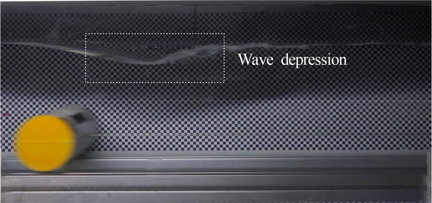
Free surface waves can be generated by water bodies (e.g., ships) or submerged bodies (e.g., submarines) that move at constant speeds (Journee and Massie, 2001). At infinite water depths, the flow around a submerged body causes various flow phenomena according to the geometry of the object and the flow velocity with no interaction with the free surface, and many relevant insights have been obtained from fluid dynamics. In contrast, the flow of a submerged body moving under the free surface forms free surface waves, causing complex physical phenomena according to the geometry, velocity, and submerged depth of the object. Therefore, many studies have been conducted to understand such phenomena. When a submerged body in the form of a cylinder, which is the most basic geometry, moves under the free surface, a jet-like flow occurs between the body and free surface, and free surface wave depression is generated behind the cylinder because of the rapid pressure change, as shown in Fig. 1 (Sheridan et al., 1997).
This depression phenomenon becomes more obvious as the submerged depth of the submerged body decreases and its velocity increases (Yi et al., 2013; Shin and Cho, 2021). In addition, a breaking wave occurs in the depression, affecting the formation of rear free surface waves (Hyun and Shin, 2000).
Studies on the geometry of rear free surface waves generated by the motion of a cylindrical submerged body have long been conducted using analytical or numerical methods, and in most of them, the free surface displacement generated behind the submerged body was calculated by applying an incident wave or flow velocity to a fixed cylinder (Dean, 1948; Ursell, 1950; Scullen and Tuck, 1995). However, this fundamentally differs from the free surface displacement caused by the direct movement of the submerged body, and the aforementioned studies had limitations in identifying the phenomena of free surface waves caused by complex interactions between the submerged body and the free surface. This is because they focused on the hydrodynamic analysis of the phenomena of free surface waves generated behind the submerged body; the actual movement of the body was not modeled. As various free surface waves caused by the acceleration of the submerged body from the stationary state are mixed with those caused by the movement of the body at a constant velocity, it is necessary to accurately simulate the motion of the submerged body through towing experiments to analyze the complex interactions affected by the geometry, velocity, and submerged depth of the body.
In general, the generation and propagation of free surface waves are calculated with potential flow that assumes the incompressible, non-rotational, and non-viscous flow of fluid (Journee and Massie, 2001). Potential flow-based numerical analysis has been commonly applied to the motion analysis of ocean waves and floating bodies using the boundary element method. In particular, time- and frequency-domain analysis for floating body motion has been widely conducted via modeling under the same conditions as an experimental tank through the numerical wave tank (NWT) technique (Uzair and Koo, 2012; Min and Koo, 2017; Min and Koo, 2022). This numerical analysis technique was used to model the motion of a submerged body and calculate free surface waves according to the submerged depth and velocity of the submerged body (Holloway and Davis, 2002; Kim et al., 2019; Seong et al., 2022). In particular, Seong et al. (2022) reproduced the free surface waves caused by the motion of a submerged body with a National Advisory Committee for Aeronautics geometry (NACA0034) using the NWT technique and validated their method through a comparison with experimental results.
In addition, various studies on the flow characteristics under submerged-body motion have been conducted using computational fluid dynamics (CFD). Various studies have been reported, in which researchers implemented changes in the free surface waves caused by the underwater motion of a simple cylinder (Mnasri et al., 2014), analyzed the dynamic characteristics of a submerged body through the adjustment of the drift angle and the angle of attack (Jeon et al., 2021), analyzed the flow noise of a submarine-shaped underwater body using CFD and computational acoustics (Ren et al., 2023), and performed spectrum analysis for the free surface waves caused by the motion of submarine- and whale-shaped underwater bodies through experiments and CFD (Liu and Guo, 2013).
To understand the complex phenomena associated with wave generation and propagation caused by the flow change between a moving submerged body and a free surface, an accurate numerical analysis conducted under various experimental conditions is required, and the phenomena must be identified through a precise experiment in which the submerged body is towed directly. Experimental research in which complex flow phenomena were measured by directly towing a submerged body is rare, and basic research is needed to analyze complex flow phenomena by directly towing a submerged body in the presence of a free surface.
In this study, acceleration and constant-velocity regions were created by directly towing a cylindrical submerged body in water to precisely identify the interactions between the body and free surface, as well as the flow changes. In addition, the generation and propagation of free surface waves were measured, and their characteristics were analyzed. In contrast to streamlined objects, a cylinder easily causes flow separation and vortices on its surface owing to fluid viscosity, making it relatively easy to identify the complex physical phenomena that occur around the cylinder. Potential flow-based numerical analysis was conducted using a two-dimensional numerical towing tank that modeled the acceleration and constant velocity of the submerged body under the experimental conditions, and the results were compared with the experimental results. By comparing the experimental measurements that included fluid viscosity and the results of potential flow-based numerical analysis, the effects of the fluid viscosity on the geometry and propagation of the free surface waves caused by the submerged body motion were identified. The objective of this study was to clarify the generation and propagation characteristics of the free surface caused by the movement of a cylindrical submerged body and provide basic data. If these basic data are accumulated, they are expected to be used for applied studies, e.g., involving the detection of underwater bodies moving under free surfaces.

2. Submerged-Body Towing Experiment and Numerical Analysis

2.1 Two-dimensional Towing Tank

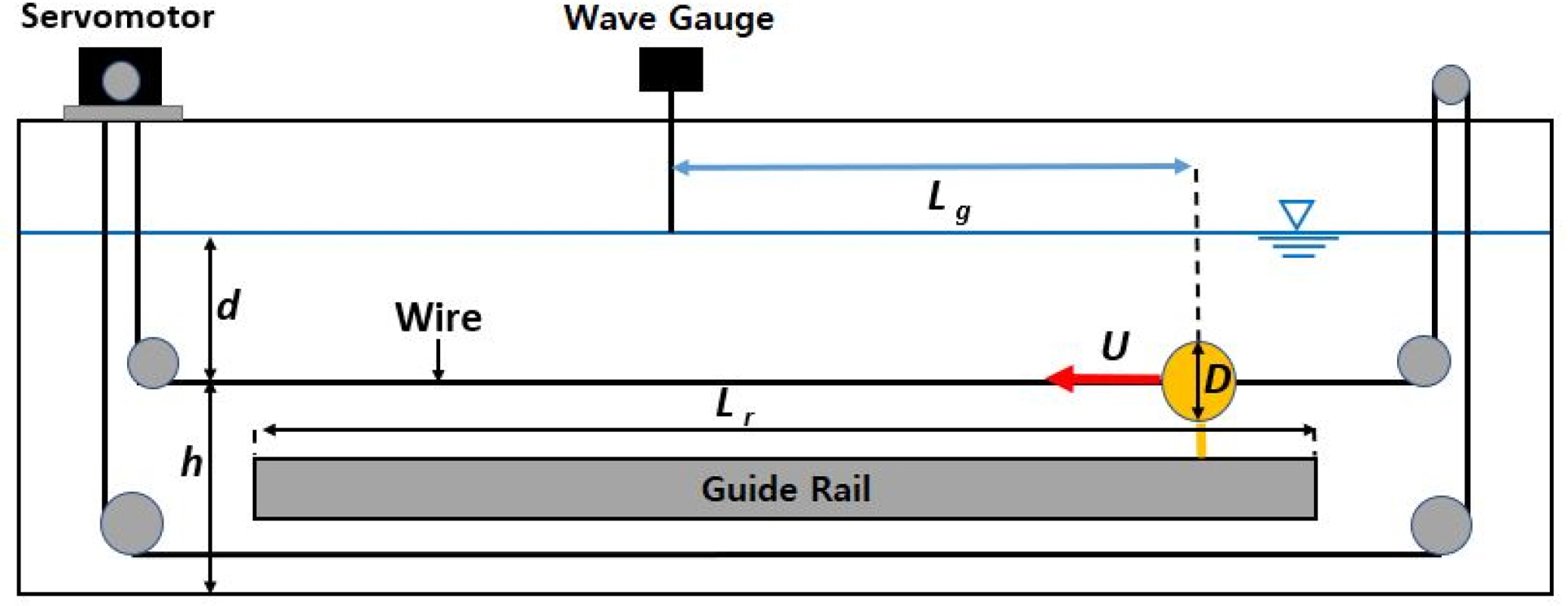
In this study, an experiment was performed using a towing tank that can directly tow a submerged body in a single fluid environment. The vertical displacement of the generated free surface waves was measured, and their propagation characteristics were analyzed according to the submerged depth of the submerged body and the towing velocity. Fig. 2 shows the cylindrical submerged body model connected to the rail support on the side wall of the two-dimensional towing tank with a wire. In the towing-tank experiment (Kim et al., 2022a), the two-dimensional submerged-body towing tank of Inha University was used. The specifications of the cylinder and towing tank are presented in Table 1. It was possible to clearly observe the displacement and propagation of the free surface because the walls of the tank are made of a transparent acrylic material, its frames are made of aluminum, and its bottom is made of polyvinyl chloride. The cylindrical submerged body was divided into upper and lower hemispheres to allow a wire to pass through, and the cylinder was formed by fastening four 3-mm-diameter bolts. The width of the submerged body was set equal to that of the two-dimensional towing tank to minimize the interference of the tank walls with the formation and propagation of free surface waves. Fig. 3 shows an overview of the towing-tank experiment. For the submerged-body towing system, the submerged body was connected to the wire installed underwater and was directly towed using the wire drum connected to the servomotor. The system did not directly interfere with the free surface, because it towed the submerged body with the wire. The system made it possible to observe the exact free surface displacement caused by the submerged-body motion, ensuring the reliability of the experimental results. Additionally, the submerged body could be accelerated from the stationary state and towed at a constant velocity.
The submerged-body towing system was used to tow the submerged body at a constant velocity. Fig. 4 shows the wire drum connected to the alternating-current (AC) servomotor installed in the towing tank. It towed the submerged body at a precise velocity along the rail installed on the tank wall by circulating the wire shown in Fig. 3. The wire connected to the submerged body passed through the centerline of the body. The tension of the wire acted on the center of gravity of the submerged body, causing translational motion. For the towing system, the towing velocity and towing distance were adjusted through the Programmable Multi Axis Controller (PMAC) software.
The free surface waves generated by the submerged body were accurately measured using a servo-type wave gauge (PCA-WH60S). This wave gauge can measure the vertical displacement of a free surface every 0.01 s (100 Hz) with a precision of up to 0.056 mm using water as a conductor. Proper tension must be maintained in the underwater wire for stable towing of the submerged body. In the experiment, the overall tension of the towing system was controlled by adjusting the pulley connected to the wire in the vertical direction.

2.2 Two-dimensional Numerical Towing Tank

To validate the experimental results, a numerical analysis was performed using a two-dimensional numerical towing tank modeled according to the experimental towing tank. Fig. 5 shows a schematic of the numerical towing tank, whose specifications are those presented in Table 1. However, the numerical towing tank did not need the underwater rail or wire, because it could move the submerged body precisely at the fixed velocity every hour. While the cylindrical submerged body was accelerated from the stationary state and subjected to the constant-velocity translational motion in the same manner as the experimental conditions, the displacement and propagation pattern of the free surface were calculated in the time domain. The two-dimensional numerical towing tank was detailed in previous works (Seong et al., 2022; Kim et al., 2022b). It was briefly described in this paper because the accuracy and reliability of the solution were verified.

2.2.1 Governing equations and boundary conditions

In the fluid field used for numerical analysis, the surface tension of the free surface was neglected, and non-viscous, incompressible, and non-rotational potential flow was assumed. Accordingly, the motion of the fluid particles in the fluid field can be described as velocity potential, and the continuity equation is satisfied. Therefore, the governing equation of the fluid field is Laplace’s equation:
(1)
2ϕ=0
where ϕ represents the velocity potential. The above governing equation can be converted into a boundary integral equation using Green’s second identity according to the boundary element method, as follows:
(2)
αϕi=Ω(Gij=ϕjnϕjGijn)ds
where α represents the solid angle, which has a value of 0.5 when the field point is located on the boundary. The two-dimensional Green’s function is Gij = −(1/2π)lnR1, where R1 represents the distance between the source point and field point distributed on the boundary of the computational domain.
There were boundary conditions for each boundary of the numerical towing tank, and linear boundary conditions were used in this study. Eqs. (3) and (4) give the linear boundary conditions of the free surface, i.e., the dynamic and kinematic boundary conditions, respectively.
(3)
ϕt+gη=0onz=0
(4)
ηt=ϕzonz=0
Here, η represents the vertical displacement of the free surface and g represents the gravitational acceleration. No penetration boundary condition was applied to the walls on both sides of the tank or the bottom, as given by Eq. (5).
(5)
ϕn=0
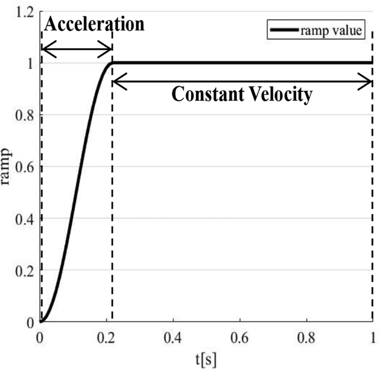
The boundary condition for the moving cylindrical submerged body is given by Eq. (6), where U represents the velocity of the body and nx is the horizontal-direction (x-direction) component of the normal vector on the submerged-body surface. The submerged body slowly accelerates and reaches a certain velocity, in the same manner as the experimental conditions. At this instance, the acceleration is given by the ramp function as shown in Eq. (7). The ramp function is applied to the initial acceleration section and the last deceleration section immediately before the submerged body stops. The ramp section is expressed by RT in Eq. (7), and it was set as 0.22 s, which was identical to that in the experiment. Fig. 6 shows the ramp function with respect to time. After passing through the ramp section, the submerged body performs translational motion at a constant towing velocity (U) in the constant-velocity region.
(6)
ϕn=ramp(Unx)onbody
(7)
ramp={1cos(πtRT)2,1{tRTt>RT

3. Comparison and Analysis of Experimental Results

3.1 Analysis of Experimental Results

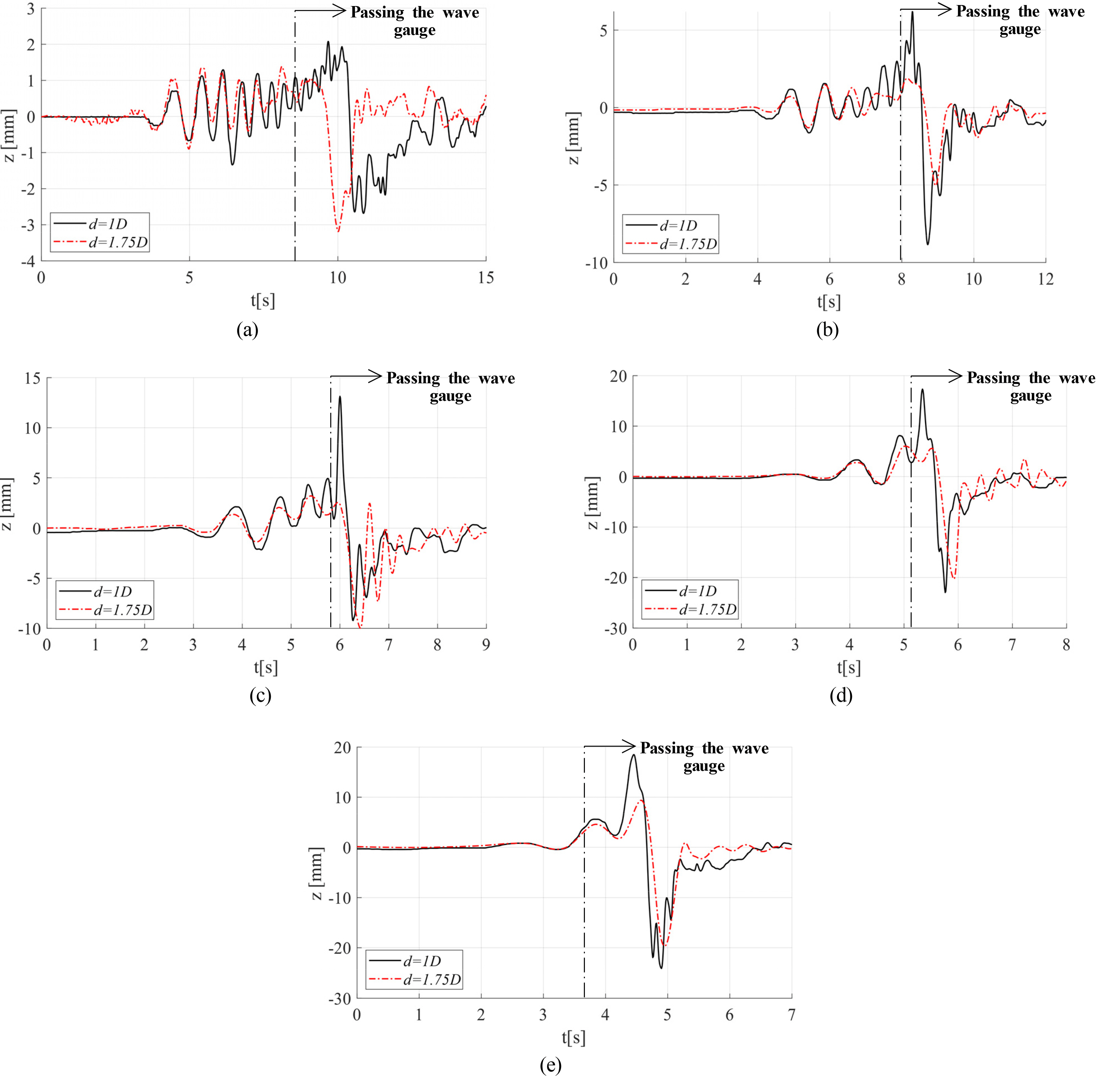
In the experiment of this study, the vertical displacement of free surface waves was analyzed, and its characteristics were identified according to the velocity and submerged depth of the submerged body. Table 2 presents the various submerged depth, velocity, and Froude number conditions examined. The waves generated in front of the submerged body by its motion were measured to identify their propagation characteristics, and the maximum wave height that occurred behind the body was measured and analyzed. Fig. 7 presents the vertical displacement of the free surface according to the body velocity in time series for submerged-body depths of d = 1D and d = 1.75D. As shown, the displacement increased as the body velocity increased, and the maximum wave height occurred behind the body.
The number of free surface waves that propagated to the front of the submerged body increased as the body approached the measuring point (the position of the wave gauge) at a low velocity. However, when the submerged-body depth was large (d = 1.75D), the maximum wave height and the number of free surface waves that propagated to the front of the body decreased. In addition, when the submerged-body depth was small (d = 1.0D), the maximum free surface displacement occurred after the submerged body passed the wave gauge owing to the occurrence of the maximum wave depression with the rapid free surface increase, and the shape of the wave was mostly lost behind the body. In contrast, when the submerged-body depth was large, the overall free surface displacement decreased, as only the maximum wave depression occurred, without a rapid increase in surface displacement. This appears to be because the jet-like flow increased behind the submerged body, which led to an increase in the displacement of the free surface as the body velocity increased (increase in Froude number) or the submerged depth decreased at a constant velocity, as reported by Shin and Cho (2021). Therefore, it can be said that the jet flow, which depends on the submerged depth and velocity of the submerged body, affects the maximum wave height.
The cause of the loss of free surface waves behind the submerged body can be inferred from the work of Hyun and Shin (2000). It is judged that as the submerged-body depth decreases, the displacement of the free surface rapidly decreases owing to wave breaking that occurs behind the body. Conversely, if the submerged-body depth increases (d = 1.75D), the degree of wave breaking that occurs behind the body is weak owing to the sufficient distance between the body and free surface, and there is room for an increase in the displacement of the free surface.
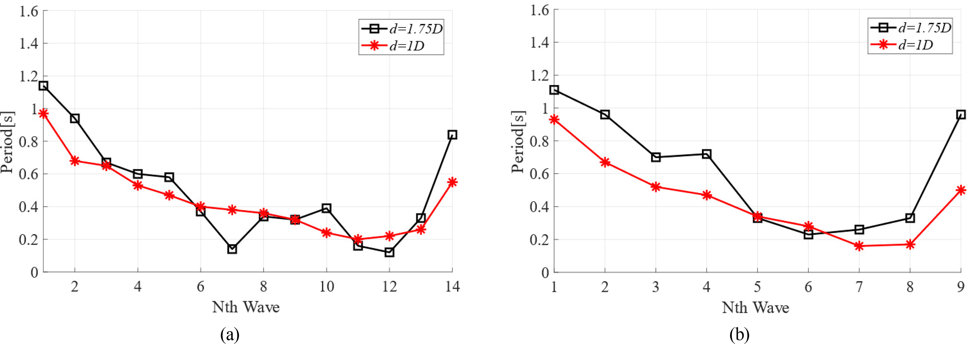
Fig. 8 shows the results of measuring and comparing the wave periods observed in front of the submerged body in order. Here, Nth Wave = 1 represents the first period measured by the wave gauge as the wave generated at the time of the acceleration of the submerged body propagated forward. As indicated by Fig. 7, the number of waves measured in front of the submerged body increased as the submerged-body depth decreased. Therefore, the number of waves measured was small when the submerged depth was large (d = 1.75D). Long-period waves were generated at the beginning when the submerged body accelerated, and then the period of the waves decreased slightly. As the submerged body approached the measuring point (the position of the wave gauge), the measured wave period decreased, but the rate of reduction gradually decreased and tended to converge to a certain value. This is because various waves were generated at different velocities until the submerged body reached a certain velocity after acceleration, and fast long-period waves among them reached the measuring point first, followed by short-period waves. The value to which the wave period converged was similar to that given by a dispersion relation (Eq. 8) that corresponds to deep water conditions. In the comparison graph, the part where the period decreases and increases suddenly represents the wave period corresponding to the maximum wave height caused by the submerged-body motion. The wave period was longer when the submerged-body depth was larger; i.e., long-period waves were generated at the maximum surface displacement that occurred behind the submerged body. In addition, the period measured in front of the submerged body was generally longer when the submerged-body depth was larger.
(8)
w2=gk
(9)
T=2πUg
Here, T represents the wave period, w represents the wave frequency, and k represents the wavenumber.
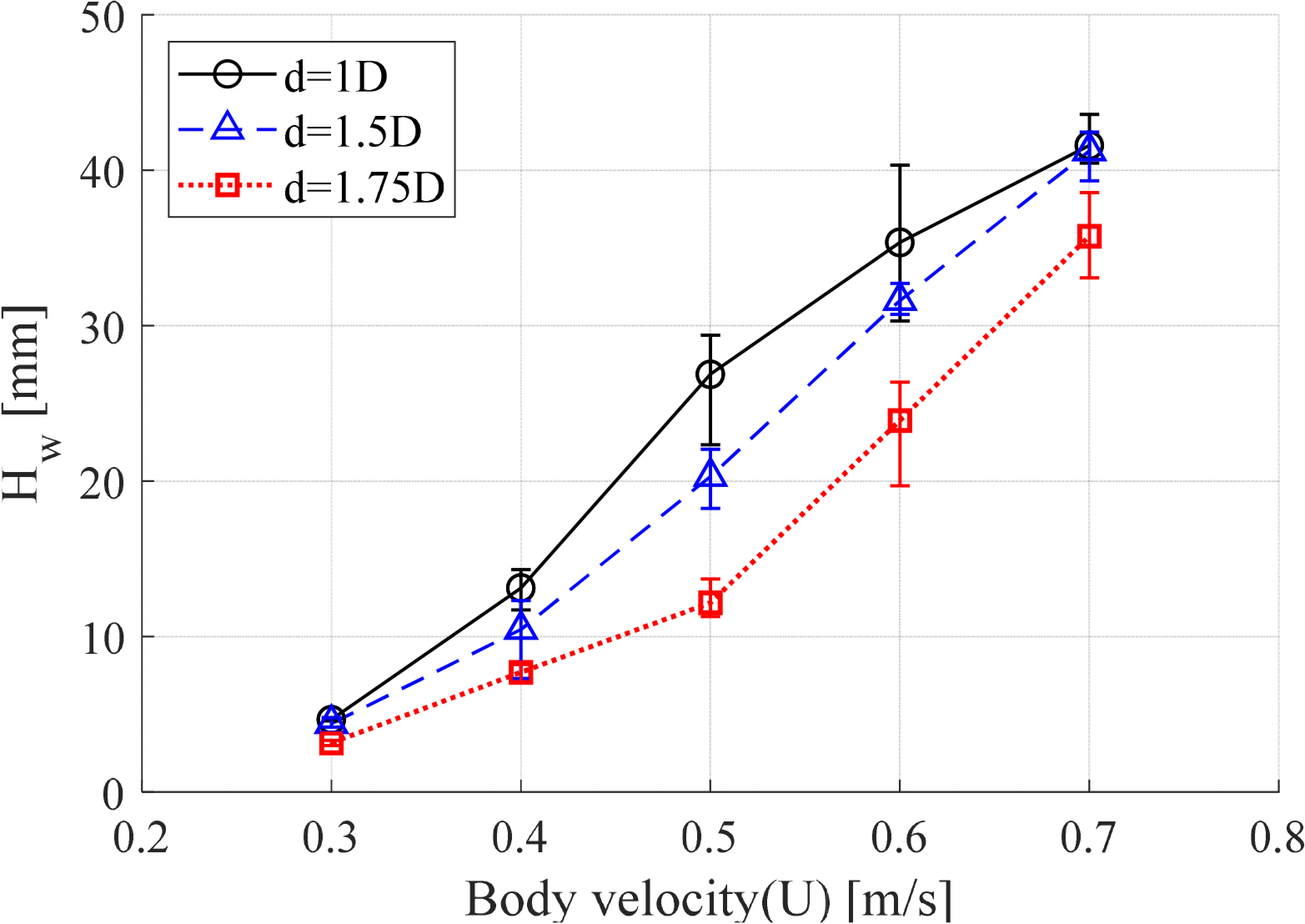
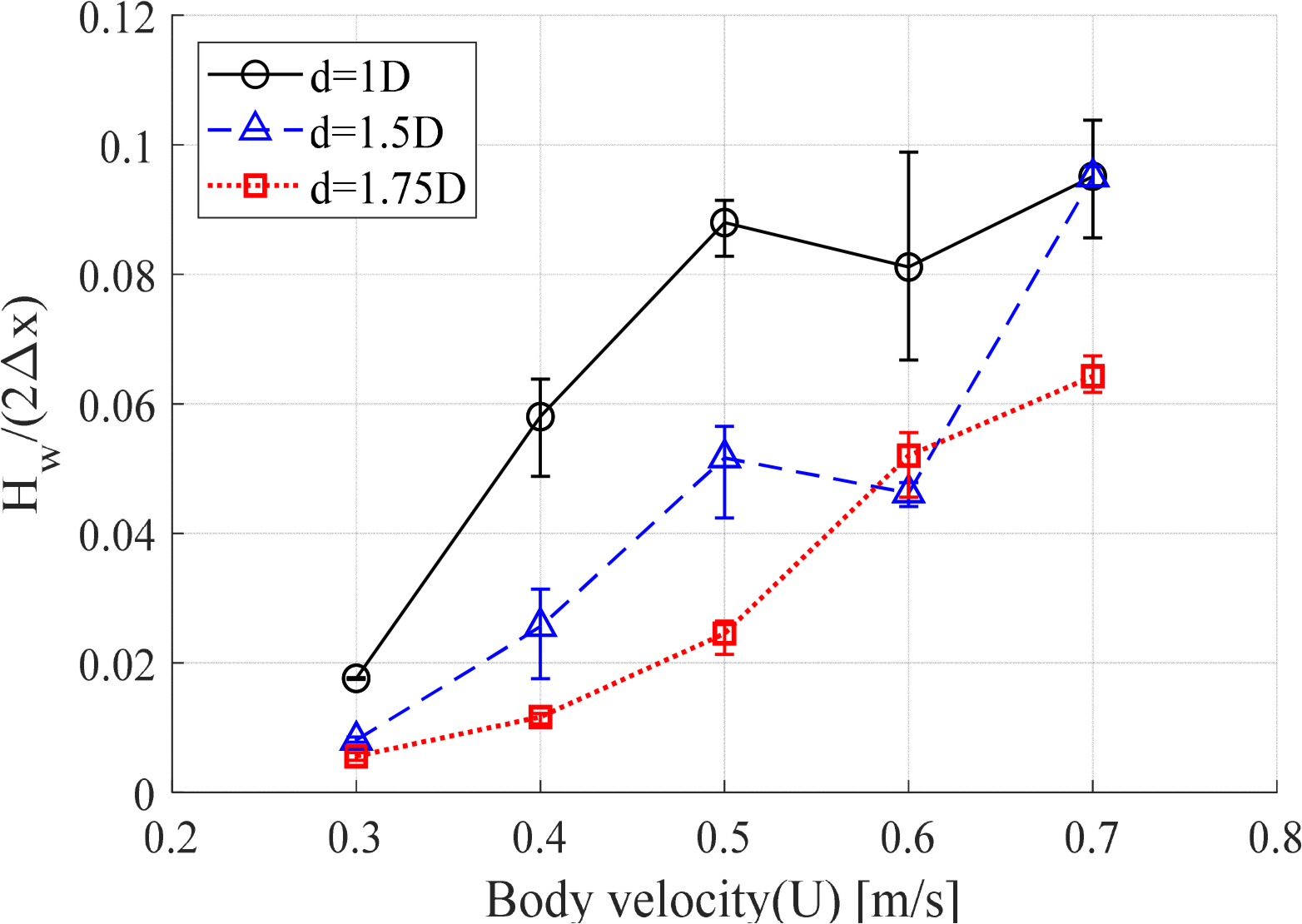
Fig. 9 shows the maximum wave height according to the submerged depth and velocity of the submerged body. As in the previous analysis, the maximum wave height tended to increase as the body velocity increased. At 0.3 m/s, which was the lowest body velocity, there was no significant difference in wave height with respect to the submerged depth. However, as the velocity increased, the wave height rapidly increased at d = 1.0D, which was the smallest submerged depth, and then decreased at a maximum velocity of 0.7 m/s. This indicates that the wave height increases with the body velocity when the submerged depth is deep enough, but the maximum wave height decreases when the velocity increases further and wave breaking occurs behind the body. If the submerged-body depth is sufficiently large, the wave-height increase is small when the velocity is low; however, the wave height is likely to increase if the velocity increases. Under the experimental conditions of this study, even if the body velocity is higher than 0.7 m/s at a submerged depth of d = 1.75D, the maximum wave height will increase further because the effect of wave breaking that occurs behind the cylinder is expected to be insignificant. This phenomenon can be more accurately understood by comparing the wave steepness at the maximum wave height, as shown in Fig. 10. Wave steepness is expressed by an equation in which the wave height is divided by the wavelength ( H2Δx,Δx=UΔt). Theoretically, when the wave steepness is close to 0.1, wave breaking occurs. When the body velocity was 0.7 m/s, the wave steepness was close to 0.1 at submerged depths of d = 1.0D and d = 1.5D. Under these conditions, the magnitude of the wave height no longer increases, because wave breaking occurs in free surface waves.

3.2 Comparison with Numerical Analysis Results

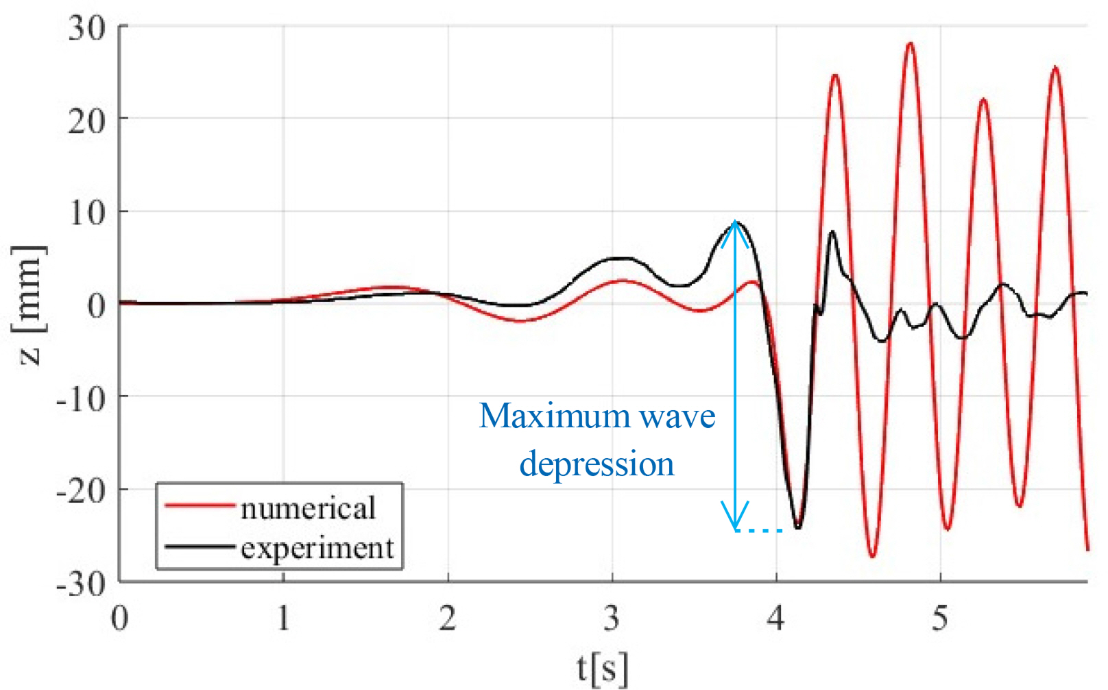
The results of the submerged-body towing experiment performed in the two-dimensional towing tank were compared with the calculation results obtained using the numerical towing tank. The benefit of the numerical technique is that the entire experimental tank can be modeled to perform calculations under the same conditions as the experiment by controlling the body velocity and reflected wave. Fig. 11 presents a comparison of the free surface displacement generated when the submerged body moved at the highest velocity (U = 0.7 m/s). As shown, the numerical analysis results generally agreed with the experimental results for the maximum wave depression of the free surface caused by the submerged-body motion. However, there was a significant difference in the free surface displacement generated behind the cylinder. This is because wave breaking occurred behind the body, and the shape of the wave was lost, as the wave steepness of the maximum wave height corresponded to the wave-breaking condition, as mentioned in the analysis of the experimental results. In contrast, in the potential flow-based numerical analysis, the waves generated by the submerged body-motion were maintained without breaking, because fluid viscosity and wave breaking were not considered. The maximum wave depression that occurs immediately after the passing of the submerged body and before the occurrence of wave breaking is the free surface displacement generated by the fluid pressure change caused by the cylinder motion. For the potential flow-based calculation, the fluid pressure change can be implemented, but it is difficult to implement the complex physical phenomena caused by fluid viscosity and wave breaking behind the submerged body. In addition, the free surface displacement that occurred in front of the submerged body was smaller than that in the experiment. This appeared to be because linear free surface boundary conditions were applied in the potential flow-based calculation; thus, the nonlinear geometry of the free surface was not reflected.
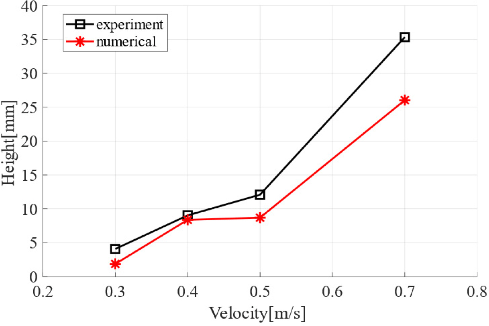
Fig. 12 presents a comparison of the magnitudes of the maximum wave depression of the free surface with respect to the velocity of the submerged body. The magnitude of the maximum wave depression corresponds to the length of the arrow in Fig. 11. The results of the experiment and numerical analysis were generally similar, and the magnitude of the maximum wave depression increased as the body velocity increased. This indicates that the formation of the maximum wave depression is affected more significantly by the kinematic factors of the submerged body and the resulting fluid pressure change than by the fluid viscosity. Therefore, the maximum wave height was accurately predicted in the potential flow-based numerical analysis, although the maximum wave height measured in the experiment slightly exceeded the numerical analysis result. This appears to be because some of the effects of fluid viscosity that could not be considered in the potential flow-based calculations were included, and the nonlinear waveforms could not be properly implemented by applying linear free surface boundary conditions.
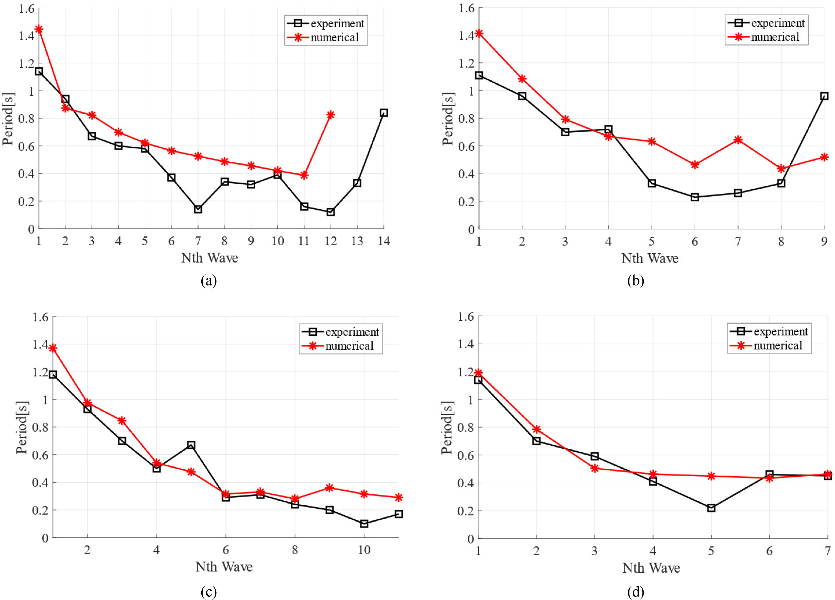
Fig. 12 presents a comparison of the measured and calculated periods of the free surface waves that propagated in front of the submerged body due to the body motion. As shown, the experimental and numerical analysis results had similar tendencies at all the body velocities. As the submerged body began translational motion and accelerated, waves with the longest period were generated and propagated first, followed by waves with gradually decreasing periods. The period of the waves generated by the submerged body at a constant velocity ultimately converged to the value given by Eq. (9), and it was confirmed that the convergence of the measurement and calculation results improved as the body velocity increased. Under all the velocity conditions, long-period waves were generated when the maximum wave depression occurred. Additionally, the rate of the wave-period increase decreased as the body velocity increased. This indicated that less long-period waves were generated as the body velocity increased, because the body quickly exited the acceleration region and entered the constant-velocity region owing to the submerged-body acceleration time being fixed at 0.22 s. Therefore, the agreement between the numerical analysis results and experimental results improved. However, the wave-period increase point differed between the experimental and numerical results, as shown in Fig. 13(a), because the numerical results and the measured data were different (Fig. 7(a)).

4. Conclusions

The complex flow phenomena around a submerged body moving under a free surface were measured using a two-dimensional submerged-body towing tank. Acceleration and constant-velocity regions were created by directly towing the cylindrical submerged body underwater. The displacement and propagation of the generated free surface waves were analyzed, and their characteristics were identified. The experimental results were compared with potential flow-based numerical analysis results to examine the effect of the fluid viscosity on the generation of free surface waves. The following conclusions are drawn.
  1. As the velocity of the submerged body increased and its submerged depth decreased, the maximum wave height of the free surface increased. However, the maximum wave height stopped increasing when the wave steepness reached the wave-breaking condition.

  2. When wave breaking occurred owing to the increase in body velocity, rapid wave loss occurred behind the body.

  3. Long-period waves were generated in the forward direction as the submerged body moved, and short-period waves were gradually generated as it moved at a constant velocity. This is because various waves were generated at different velocities until the submerged body reached a certain velocity after acceleration, and the fastest long-period waves among them reached the measuring point first, followed by short-period waves.

  4. In the potential flow-based numerical analysis results, the maximum wave depression was generally accurately predicted because it was possible to implement the fluid pressure change caused by the submerged-body motion, but it was difficult to implement the complex physical phenomena caused by fluid viscosity and wave breaking behind the submerged body.

To more precisely analyze the generation and propagation characteristics of free surface waves caused by submerged-body motion, it is necessary to investigate the changes in free surface waves due to changes in the submerged-body geometry and acceleration region, as well as high-speed motion, in the future. This will make it possible to obtain basic data that can be applied to the detection of submerged bodies that move near free surfaces.

Conflict of Interest

Weoncheol Koo serves as a editorial board member of the Journal of Ocean Engineering and Technology, but he had no role in the decision to publish this article. No potential conflict of interest relevant to this article was reported.

Funding

This research was supported by the Basic Research Project of Science and Engineering, National Research Foundation of Korea (NRF-2018R1D1A1B07040677).

Fig. 1.
Free surface wave depression caused by submerged cylinder motion
ksoe-2023-006f1.jpg
Fig. 2.
Submerged cylinder installed in a two-dimensional mini-towing tank
ksoe-2023-006f2.jpg
Fig. 3.
Experimental setup for towing the submerged cylinder
ksoe-2023-006f3.jpg
Fig. 4.
AC servomotor and wire drum for towing the submerged body
ksoe-2023-006f4.jpg
Fig. 5.
Computational domain of the two-dimensional numerical towing tank
ksoe-2023-006f5.jpg
Fig. 6.
Ramp function for towing velocity
ksoe-2023-006f6.jpg
Fig. 7.
Time series of surface elevations for different velocities: (a) U = 0.3 m/s; (b) U = 0.4 m/s; (c) U = 0.5 m/s; (d) U = 0.6 m/s; (e) U = 0.7 m/s
ksoe-2023-006f7.jpg
Fig. 8.
Comparison of wave periods measured in order: (a) U = 0.3 m/s; (b) U = 0.4 m/s
ksoe-2023-006f8.jpg
Fig. 9.
Comparison of the maximum wave height for various body velocities
ksoe-2023-006f9.jpg
Fig. 10.
Comparison of the wave steepness for various body velocities at the maximum wave height
ksoe-2023-006f10.jpg
Fig. 11.
Comparison of wave elevations for d = 1.75 D and U = 0.7 m/s
ksoe-2023-006f11.jpg
Fig. 12.
Comparison of the maximum wave depression values for various body velocities
ksoe-2023-006f12.jpg
Fig. 13.
Comparison of wave periods measured and calculated in order at d = 1.75D: (a) U = 0.3 m/s; (b) U = 0.4 m/s; (c) U = 0.5 m/s; (d) U = 0.7 m/s
ksoe-2023-006f13.jpg
Table 1.
Dimensions of the two-dimensional towing tank and submerged body
Object Parameter Dimension (m)
Towing tank Tank length (L) 5.8
Tank width (B) 0.2
Water depth (H) 0.77
Rail length (Lr) 4
Wave gauge location (Lg) 2.8

Submerged cylinder Body diameter (D) 0.084
Body width (W) 0.19
Body position from tank bottom (h) 0.395
Table 2.
Experimental conditions
Parameter Dimensions
Submerged-body depth (d) 1D, 1.5D, 1.75D (m)
Body velocity (U) 0.3–0.7 (m/s)
Froude number ( Fr=UgD) 0.330–0.771
Reynolds number ( Re=ρUDμ) 14,157–33,033
Towing distance (Lr) 4 (m)

References

Dean, W.R. (1948). On the reflection of surface waves by a submerged circular cylinder. Mathematical Proceedings of the Cambridge Philosophical Society, 44(4), 483-491. https://doi.org/10.1017/S0305004100024506
crossref
Holloway, D. S., & Davis, M. R. (2002). Green function solutions for the transient motion of water sections. Journal of Ship Research, 46(2), 99-120. https://doi.org/10.5957/jsr.2002.46.2.99
crossref
Hyun, B. S., & Shin, Y. H. (2000). On the viscous flow around breaking waves generated by a submerged cylinder (Part 2: Aspects of viscous flow). Journal of the Society of Naval Architects of Korea, 37(1), 91-98.

Jeon, M. J., Mai, T. L., Yoon, H. K., Ryu, J. W., Lee, W. H., & Ku, P. M. (2021). Evaluation of dynamic characteristics for a submerged body with large angle of attack motion via CFD analysis. Journal of Ocean Engineering and Technology, 35(5), 313-326. https://doi.org/10.26748/KSOE.2021.063
crossref
Journee, J. M. J., & Massie, W. W. (2001). Offshore hydromechanics. 1st ed Delft University of Technology.

Kim, D. E., Min, E. H., Koo, W. C., & Kim, Y. G. (2019). Numerical analysis of free surface by motion of a submerged body in fluids. Proceedings of KOASTS, 2019, 90-93.

Kim, J. B., Koo, W. C., & Min, E. H. (2022a). An experimental study of towing a circular submerged body in a single-layer fluid. Proceedings of KOASTS, 2022, 264-265.

Kim, J. B., Koo, W. C., & Min, E. H. (2022b). Comparison of numerical simulation and experiment of a towed submerged cylinder in a single fluid. Proceeding of the Annual Autumn Conference 2022, SNAK. 418-422.

Liu, T. L., & Guo, Z. M. (2013). Analysis of wave spectrum for submerged bodies moving near the free surface. Ocean Engineering, 58, 239-251. https://doi.org/10.1016/j.oceaneng.2012.10.003
crossref
Min, E. H., & Koo, W. C. (2017). Hydrodynamic characteristics of internal waves induced by a heaving body in a two-layer fluid. Ocean Engineering, 145(15), 290-303. https://doi.org/10.1016/j.oceaneng.2017.09.017
crossref
Min, E. H., & Koo, W. C. (2022). Comparison of wave diffraction forces on a surface-piercing body for various free-surface grid update schemes. Ocean Engineering, 259(1), 111912. https://doi.org/10.1016/j.oceaneng.2022.111912
crossref
Mnasri, C., Hafsia, Z., Omri, M., & Maalel, K. (2014). A moving grid model for Simulation of free surface behavior induced by horizontal cylinders exit and entry. Engineering Applications of Computational Fluid Mechanics, 4(2), 260-275. https://doi.org/10.1080/19942060.2010.11015315
crossref
Ren, Y., Qin, Y., Pang, F., Wang, H., Su, Y., & Li, H. (2023). Investigation on the flow-induced structure noise of a submerged cone-cylinder-hemisphere combined shell. Ocean Engineering, 270, 113657. https://doi.org/10.1016/j.oceaneng.2023.113657
crossref
Scullen, D., & Tuck, E. O. (1995). Nonlinear free-surface flow computations for submerged cylinders. Journal of Ship Research, 39(3), 185-193. http://pascal-francis.inist.fr/vibad/index.php?action=getRecordDetail&idt=3668054

Seong, W. J., Koo, W. C., & Min, E. H. (2022). Numerical and experimental study on free-surface wave generation by a submerged moving body in a towing tank. Ocean Engineering, 252(15), 1-12. https://doi.org/10.1016/j.oceaneng.2022.111200
crossref
Sheridan, J., Lin, J. C., & Rockwell, D. (1997). Flow past a cylinder close to a free surface. Journal of Fluid Mechanics, 330(10), 1-30. https://doi.org/10.1017/S002211209600328X
crossref
Shin, D. M., & Cho, Y. (2021). Concurrent vortex-shedding and surface-wave phenomena around a horizontal circular cylinder close to a free surface. Proceeding of KSME Conference, 33-35.

Ursell, F. (1950). Surface waves on deep water in the presence of a submerged circular cylinder. I Mathematical Proceedings of the Cambridge Philosophical Society, 46(1), 141-152. https://doi.org/10.1017/S0305004100025561
crossref
Uzair, A. S., & Koo, W. C. (2012). Hydrodynamics analysis of a floating body with an open chamber using a 2D fully nonlinear numerical wave tank. International Journal of Naval Architecture and Ocean Engineering, 4(3), 281-290. https://doi.org/10.2478/IJNAOE-2013-0096
crossref
Yi, H. J., Shin, H. K., & Yoon, B. S. (2013). Study on flow around circular cylinder advancing beneath free surface. Journal of Ocean Engineering and Technology, 27(5), 16-21. http://dx.doi.org/10.5574/KSOE.2013.27.5.016
crossref


ABOUT
BROWSE ARTICLES
ARTICLE CATEGORY

Browse all articles >

PUBLICATION ETHICS
FOR CONTRIBUTORS
Editorial Office
President Office BD Rm. 1302, 13 Jungang-daero 180beon-gil, Dong-gu, Busan 48821, Republic of Korea
Tel: +82-51-759-0656    Fax: +82-51-759-0656    E-mail: ksoehj@ksoe.or.kr                

Copyright © 2024 by The Korean Society of Ocean Engineers.

Developed in M2PI

Close layer
prev next