
1. Introduction
The technology for utilizing maritime space has been consistently studied for purposes such as securing food resources through fisheries and developing ocean resources like seabed oil and natural gas. In particular, a recent focus on eco-friendly energy has resulted in active research into the development of offshore structures for renewable energy generation. Specifically, these offshore structures for renewable energy generation are generally operated as large-scale complexes. Thus, various numerical methods have been developed to analyze the entire system, and studies have also been conducted to improve the performance of these structures by analyzing their configuration and the effect of wave load conditions. Park and Choung (2023) conducted a direct strength assessment with the main load factors of acceleration and nacelle thrust in a 10-MW offshore wind power system based on the internal code HydroQus (Yoon and Choung, 2023). They analyzed vulnerable parts of the substructure based on the assessment results. Song et al. (2014) analyzed the effect of initial conditions on the transient response characteristics of floating wind turbines. Chen et al. (2021) researched a method to predict fatigue life with approximately 2% error compared to the complete elastic model, utilizing aerodynamic decoupling and a mode-based order reduction method. Kim et al. (2022b) conducted a numerical analysis study, applying second order wave loads, nonlinear FroudeŌĆōKrylov forces, and the damping force of the power take-off (PTO) system in a tension-leg platform (TLP)-based hybrid power generation platform with excellent motion performance in waves.
Ghigo et al. (2022) selected Lampedusa Island as the case study and performed a performance assessment of a floating photovoltaic power generation system through numerical analysis of loads caused by waves and currents. Na et al. (2021) compared and analyzed the results of model tests and field performance test for the unit platforms designed to construct large-scale floating photovoltaic power generation systems, reviewing key performance parameters such as sway reduction and stability. The Korea Research Institute of Ships & Ocean Engineering (KRISO) developed multi-linked floating offshore structures composed of numerous floating bodies connected by beams, allowing for expansion through inter-unit connections. The characteristics of these multi-linked floating offshore structures vary according to several design elements, such as the size of the structure, initial tension of mooring lines, and method of unit structure connection. Among these design components, the magnitude of the initial tension in the mooring lines can significantly alter the wave loads acting on the structure and, consequently, the motion and structural response. Therefore, reviewing the structureŌĆÖs response to wave loads and designing sufficient initial mooring line tension is essential.
In addition, as the motion, structural response and the characteristics of the mooring line tension change according to the connection method between unit structures, it is necessary to analyze the response of structures for the safe design of super-large systems composed of multi-linked floating offshore structures. Thus, we performed a fluidŌĆōstructure coupled numerical analysis to examine the impact of the connection condition (a major design element) on the motion and structural response of the multi-linked floating offshore structures developed by the KRISO. Considering multi-linked floating offshore structures have numerous floating bodies, they require extensive computational resources; hence, the wave loads were modeled as nodal forces to reduce the computational cost. Based on this fluidŌĆōstructure coupled numerical analysis technique, various fluidŌĆōstructure coupled numerical analyses were performed under different wave load conditions and three different connection conditions to analyze the effect of connection conditions on the expansion of the entire system. This analysis included a comparative study of six degrees of freedom motion characteristics, the maximum magnitude and occurrence location of the dominant bending stress in the multi-linked floating offshore structures, and the tension in the mooring lines.
2. FluidŌĆōStructure Coupled Analysis for Multi-Linked Floating Offshore Structures
2.1 Multi-Linked Floating Offshore Structures for Photovoltaic Generation Systems
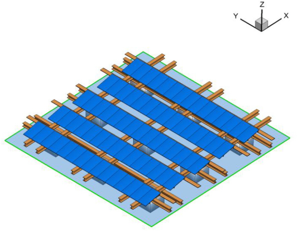
Offshore photovoltaic generation systems typically have multiple interconnected modules. As illustrated in Fig. 1, a numerical analysis was conducted on the multi-linked floating offshore structures composing a 2-MW-class offshore photovoltaic power generation system. The system in Fig. 1 is interconnected through 72 modules, installed in a sea area with a water depth of 9 m, and linked to 204 mooring lines in a taut mooring configuration. These multi-linked floating offshore structures can be expanded by joining unit structures, as depicted in Fig. 2, and each unit comprises 9 floats and 36 beam structural members. This study examined a structureŌĆÖs motion and structural responses based on numerical analyses and model testing results of a 2-MW-class offshore photovoltaic power generation system.
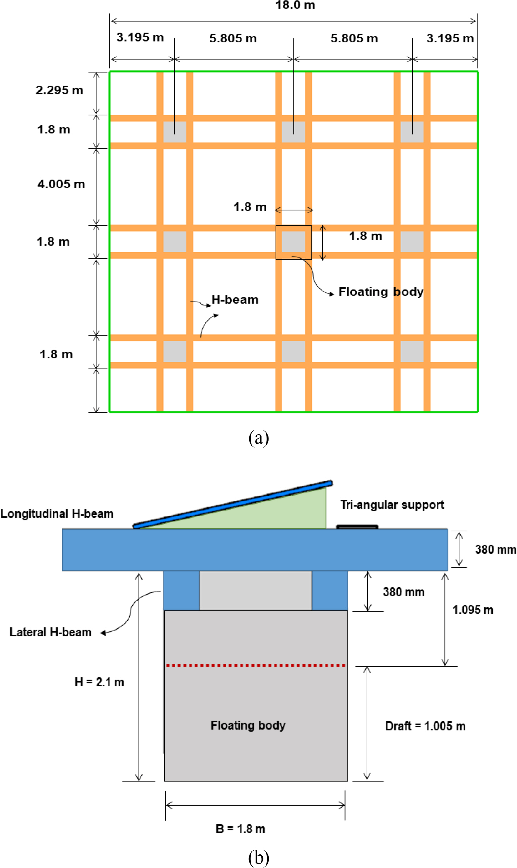
Furthermore, we researched structures with two-unit structures to analyze the effect of the mooring line tension and structural response, depending on the connection method between the unit structures of the multi-linked floating offshore structures. Detailed specifications of the unit structures are presented in Fig. 3 and Table 1. For mooring lines, similar to the 2-MW-class system, 36 lines are connected in a taut mooring method.
2.2 Numerical Analysis of FluidŌĆōStructure Interaction for Multi-Linked Floating Offshore Structures
In this research, a fluidŌĆōstructure coupled numerical analysis was performed to consider the interactions among floating bodies, beam structural members, and mooring lines. Hydrodynamic analysis was initially conducted to calculate wave loads acting on the multi-linked floating offshore structures, employing a high-order boundary element method (HOBEM) that improves accuracy and convergence compared to conventional boundary element methods. The analysis considered the interaction between each buoyancy body. It included hydrodynamic characteristics, such as wave loads in the frequency domain, added mass, and damping, as calculated in Eq. (1) below (Kim et al., 2013).
Here, [MB] and [Madd] represent the mass of the floating body and added mass, respectively, [CB] denotes hydrodynamic damping, an [KB] represents hydrodynamic restoring stiffness. x(Žē) and fwave (Žē) signify the motion of the floating body and wave load, depending on the wave frequency (Žē).
After converting the wave loads and hydrodynamic characteristics calculated in the frequency domain to the time domain, they were applied to a finite element model as load conditions. Finally, a structural analysis in the time domain was performed with the motion equation as in Eq. (2).
Here, [M], [C], and [K] denote the mass, damping, and stiffness of the structural analysis model for the multi-linked floating offshore structures, and u(t) represents displacement in the time domain. The motion equation of Eq. 2 applied the representative implicit numerical method, the Newmark algorithm, for the numerical analysis.
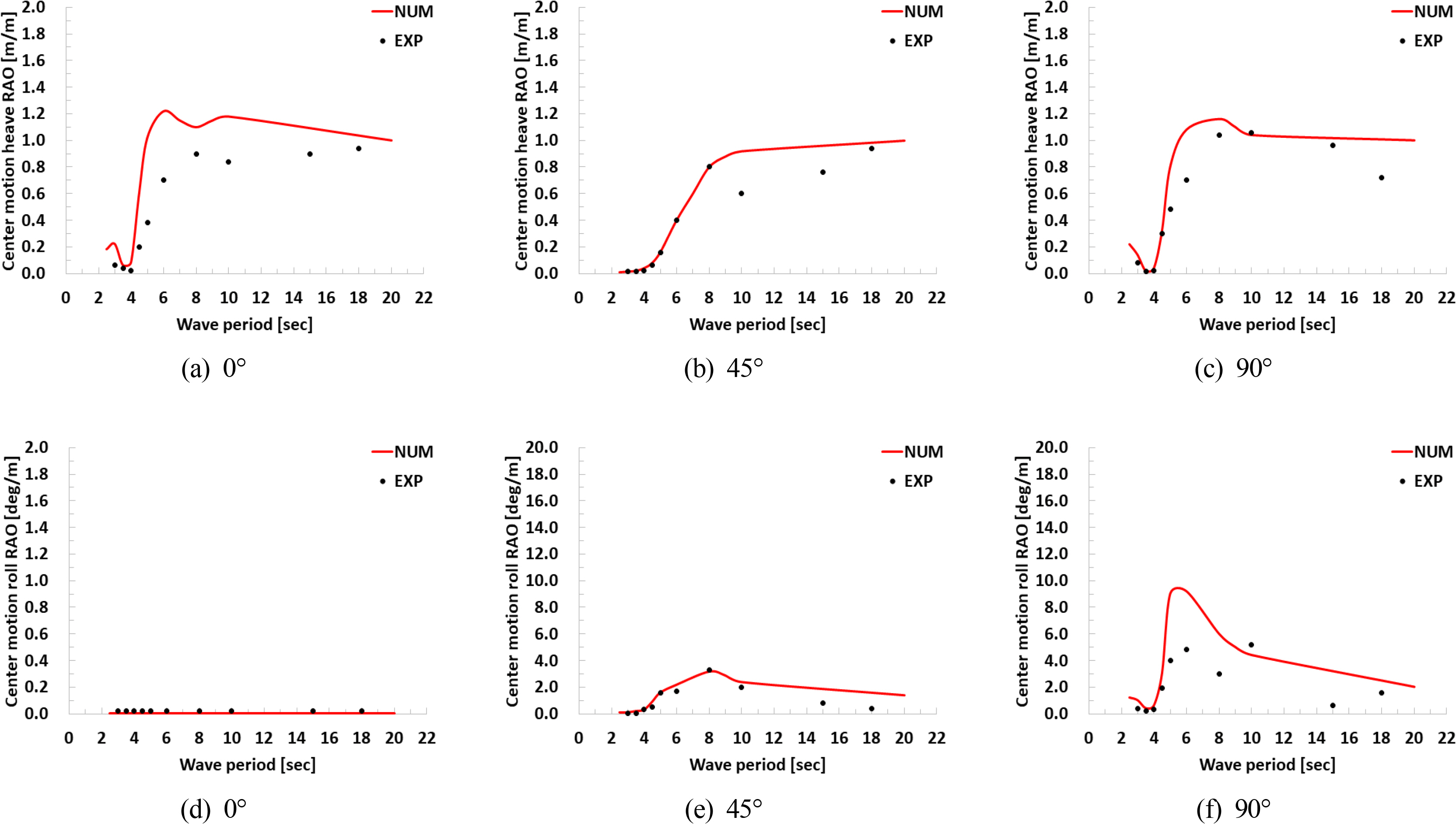
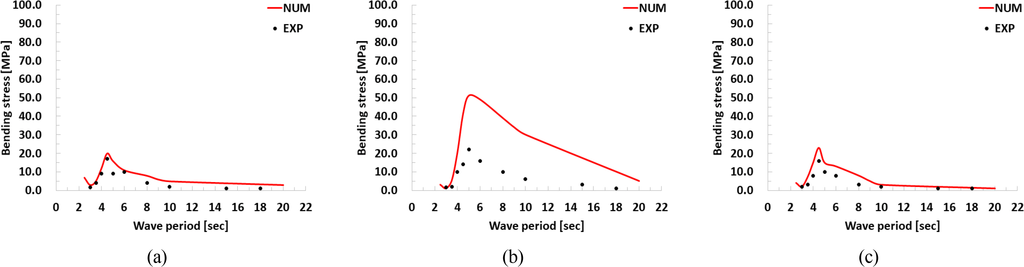
Commencing with an analysis of a 2-MW-class offshore photovoltaic power generation system, numerical modeling was conducted as depicted in Fig. 4(a), followed by fluidŌĆōstructure coupled analysis. In addition, model tests were conducted in the ocean engineering basin at KRISO, as depicted in Fig. 4(b), facilitating the measurement of the constructionŌĆÖs motion and structural responses (Kim, 2023). These model tests were executed at a 1/15 model scale; the floating bodies of the structure were fabricated with expanded polypropylene, and the beam connectors were made of aluminum. Furthermore, the stiffness of the mooring lines was simulated with springs, and a separate anchor system was fabricated and connected to the mooring lines. To measure the six degrees of freedom motion response at the center and edges of the entire structure and the structural response, the bending stresses were scaled to record the strain on the beam connectors where maximum stress occurred. A series of regular, irregular wave tests for head seas, oblique seas, and beam seas was conducted to measure the structureŌĆÖs response to compare with numerical analysis results. The numerical analysis and model test results for the motion and structural response of the target structure are illustrated in Figs. 4 and 5. The numerical analysis results did not significantly differ in response magnitude or overall trend compared to the model test results. The heave and roll motion responses in Fig. 5 represent the numerical and experimental measurement results at the systemŌĆÖs central position, the most significant translational and rotational movements among the six degrees of freedom motions. Unlike the heave response, which demonstrated a similar trend across all wave directions, the roll motion had the most significant response perpendicular to the wave direction. In the case of bending stress, as illustrated in Fig. 6, the model test results were almost identical across all wave directions. However, a considerable discrepancy with numerical results was noted under oblique wave conditions at 45┬░, attributed to factors such as tolerances in the model fabrication process and limitations in realizing the ideal connection conditions at the joints.
Moreover, under oblique wave conditions, discontinuous stress occurred at the connections between the unit structures, leading to a significantly greater stress difference than other wave conditions. As the unit structures expanded, the cumulative error caused by the discontinuous stress at the connections became apparent, explaining the variation in the bending stress of the beams under the beam sea conditions in Fig. 6. As the above research findings indicate, the design of connections is critically important for the overall system of multi-linked floating offshore structures, which comprises numerous interconnected unit structures. Consequently, we conducted a numerical analysis on multi-linked floating offshore structures with two-unit structures to analyze the effects of movement and structural responses according to connection conditions, focusing specifically on variations in mooring line tensions and structural response differences based on the connection methods between unit structures.
2.3 Numerical Model
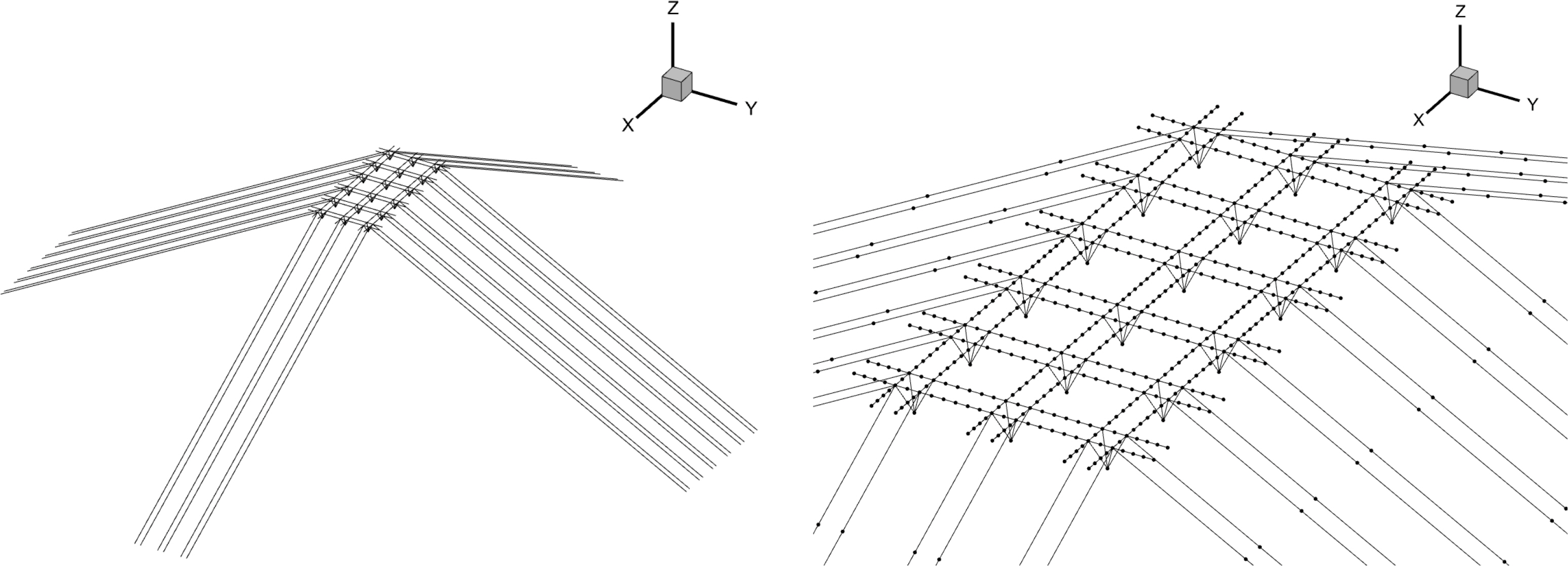
The numerical model for the multi-linked floating offshore structures can be divided into two parts: a panel model for calculating wave loads and hydrodynamic characteristics acting on the floating structures and a structural analysis model for computing the responses of structural beams and mooring lines. As illustrated in Fig. 7, the panel model includes 432 high-order elements with nine nodes each. The structural analysis model comprises 1056 beam elements representing structural members and mooring lines, as depicted in Fig. 8. In the case of the structural analysis model, the floating structure is modeled as a single node located at the center of the floating structure. The wave loads calculated through the hydrodynmic analysis are integrated over the area of high-order elements comprising the floating structure and applied as point loads to the node. In addition, to transmit the wave loads to the beam structural members without energy loss, each node is modeled with four beam elements, which has ver large stiffeness, effectively linking the beam elements to the node. This approach significantly reduces the computational cost of numerical calculations as the number of multi-linked floating offshore structures increases. The connections between unit structures were modeled with various connection conditions, such as hinges. In contrast, the mooring lines were modeled as beam elements incorporating design tensions and stiffness of the lines. Also, fixed translational degree of freedoms were applied to the nodes as boundary conditions representing the anchors of the mooring lines.
3. Structural Safety Assessment of Multi-Linked Floating Offshore Structures
Through fluidŌĆōstructure coupled analysis of the aforementioned numerical model, we calculated the motion and structural responses of the structures with wave load condition presented in Table 2. The response amplitude operator (RAO) for motion and structural response were derived and analyzed based on the analysis results under regular wave conditions. Furthermore, numerical analyses under irregular wave conditions were conducted to evaluate the structural safety based on maximum bending and shear stresses and mooring line tensions affecting the structural beam and mooring lines. We also reviewed the locations where each structural response was maximized.
3.1 Motion Response Characteristics of Multi-Linked Floating Offshore Structures
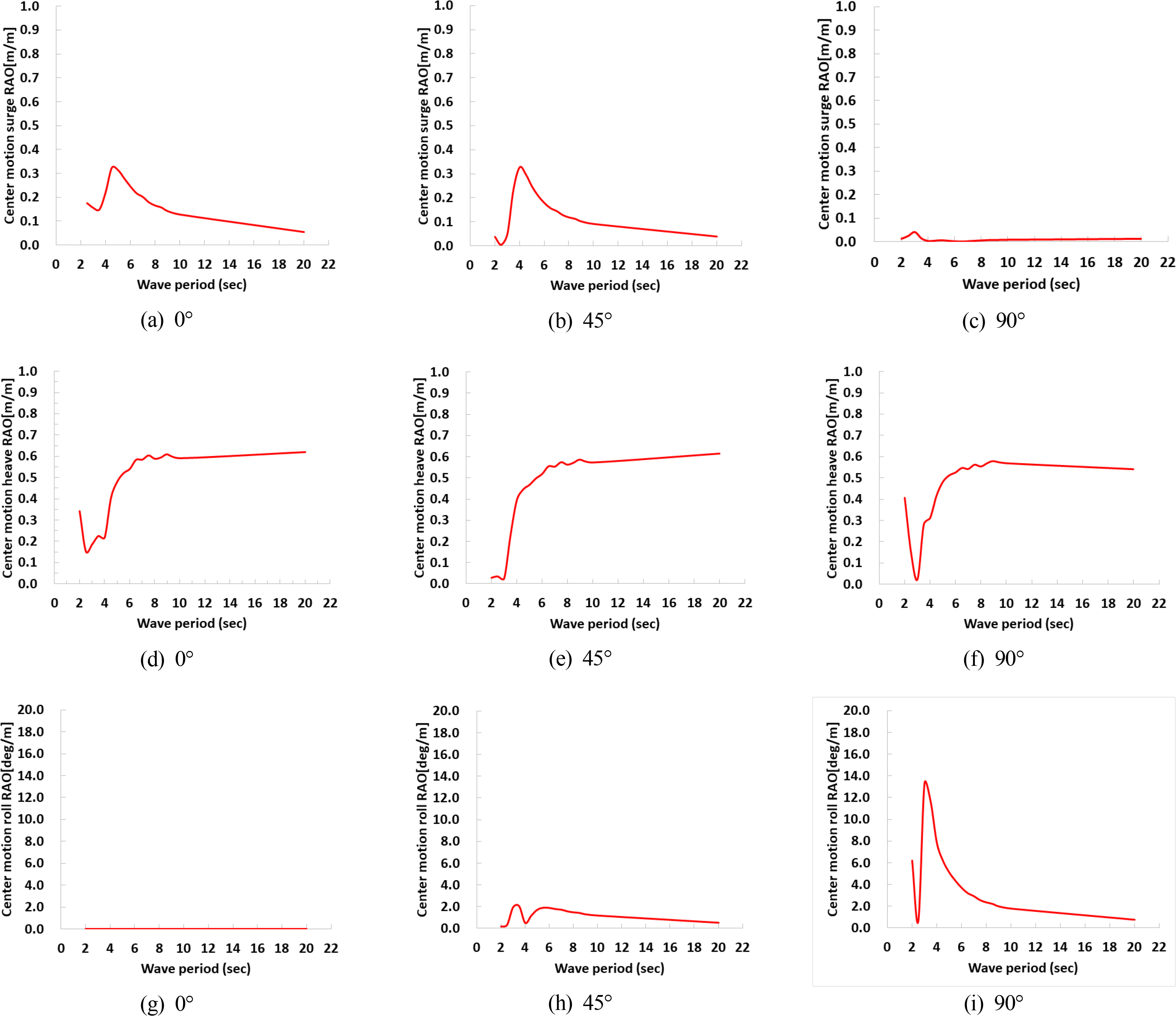
The motion response of multi-linked floating offshore structures was calculated from the center of gravity of each unit structure and is represented in Fig. 9. Excluding the heave motion, all other motions exhibit their maximum response between 2.0 and 6.0 s, decreasing as the wave period lengthens. Heave demonstrates small variation with wave direction, converging towards a 0.5-m as the wave period extends into longer durations. Yaw motion was almost non-existent across all wave directions and periods.
3.2 Structural Response Characteristics and Safety Assessment of Structural Beams
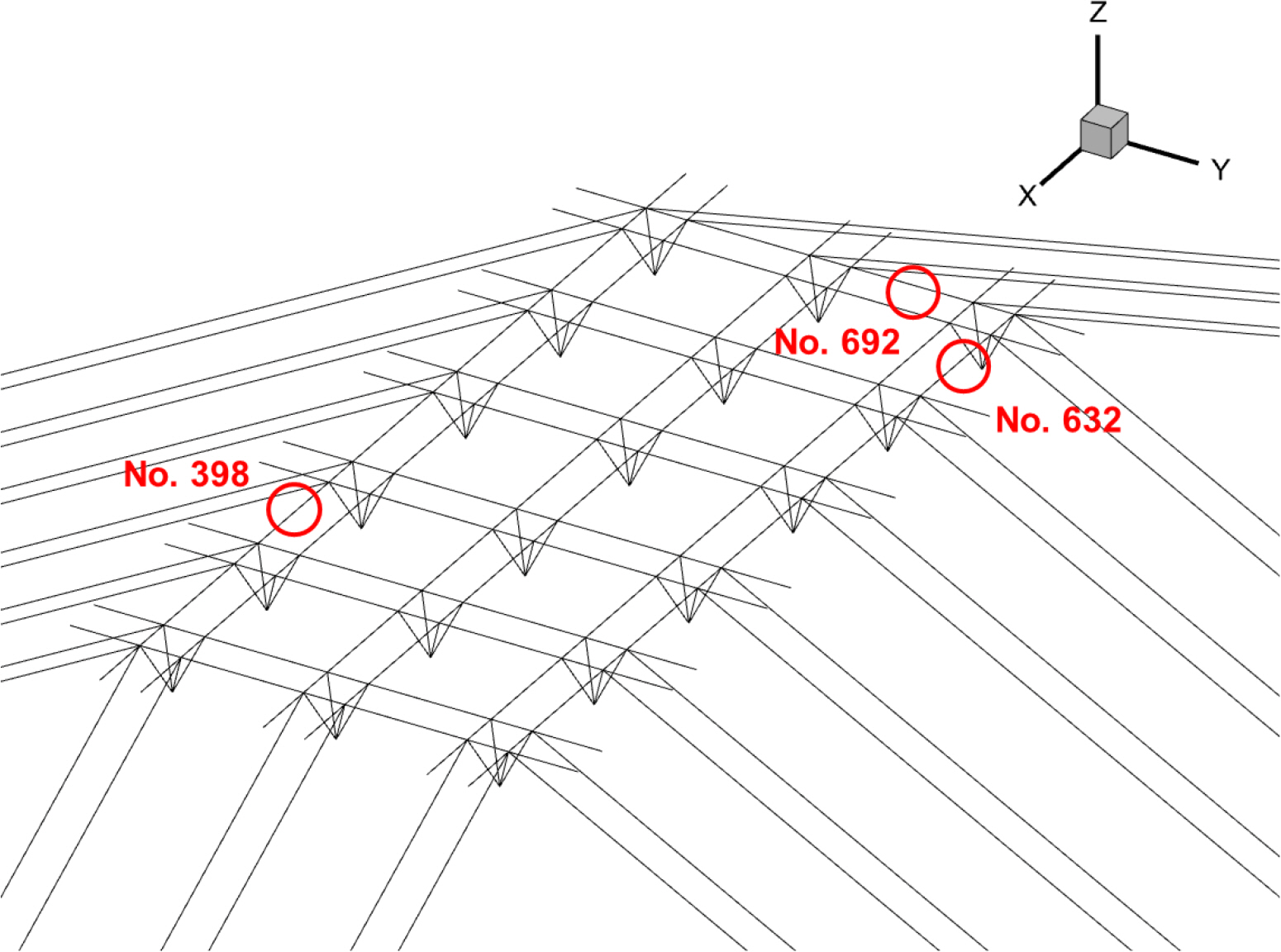
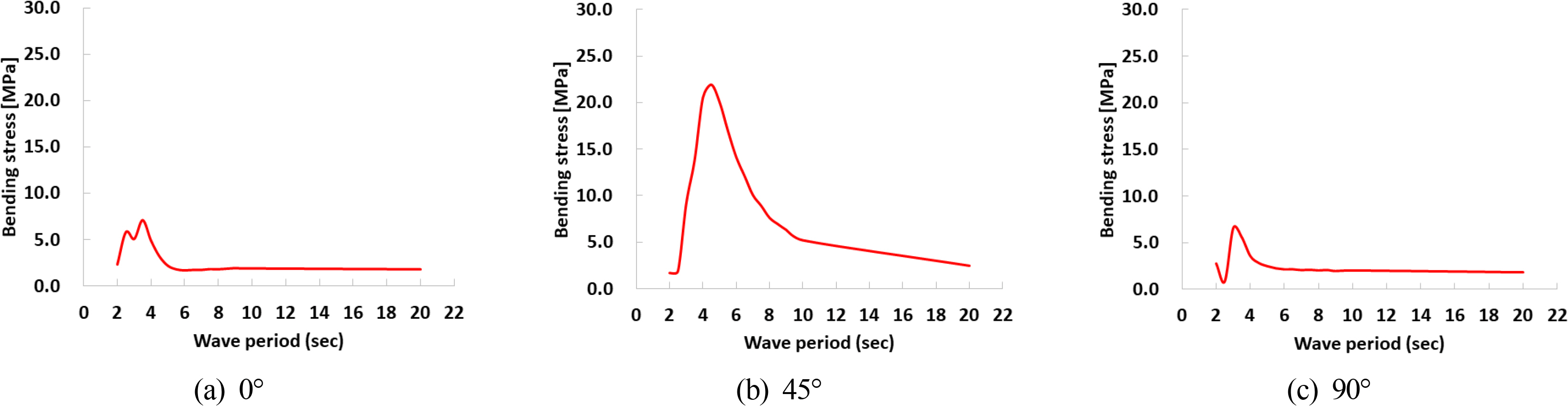
For structural beams, numerical analyses under irregular wave conditions were conducted to determine the maximum values of bending stresses locations that the maximum value occurred. Furthermore, the maximum bending stress was utilized to assess the safety regarding the allowable stress and fatigue life of the multi-linked floating offshore structures. The maximum bending stress values for each wave direction, the element number where maximum bending stress occurred, and the fatigue life for these elements are presented in Table 3. The locations of these elements are presented in Fig. 10. All maximum bending stresses for each wave direction, as depicted in Fig. 11, are below the allowable stress of 196 MPa for aluminum materials, thus satisfying the allowable stress criteria. For fatigue life calculated with the rain flow counting method from the time history under irregular waves, the results indicated an almost infinite fatigue life well within the 25-year standard. At 0┬░ wave direction, the maximum bending stress was predominantly observed in the longitudinal structural beams located at the edges of the structure where mooring lines are connected. At 45┬░ wave direction, it occurred in the beam structural members adjacent to the connection joints, and in both directions, it was found in the longitudinal structural beams. At 90┬░ wave direction, the maximum bending stress appeared in the transverse structural beams. The smallest maximum bending stress was at 0┬░, and the largest at 45┬░. The lower stress at 0┬░ can be attributed to the greater rotational movement due to the hinged connections compared to other wave directions, affecting the constraint conditions of the beam.
4. Analysis of Effect of Connection Methods on Characteristics of Multi-Linked Floating Offshore Structures
4.1 Influence of Connection Methods Between Unit Structures on Bending Stress
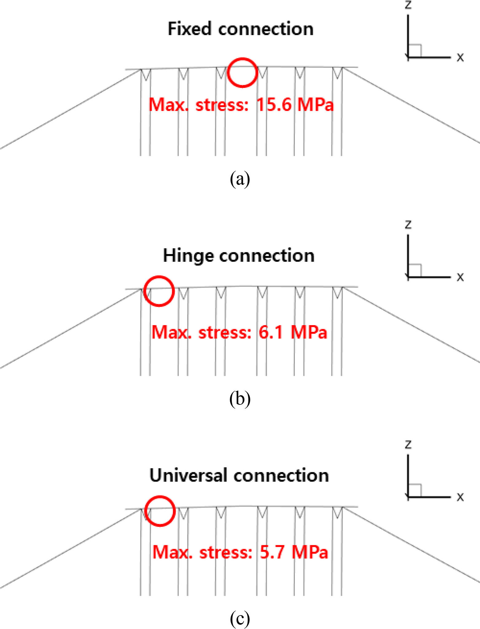
Numerical simulations were conducted under irregular wave conditions progressing in the X direction with varying connection conditions to analyze the structural response characteristics depending on the connection methods at the joints between unit structures of multi-linked floating offshore structures. Three different types of connections were considered: 1) a fixed connection, which constrains all rotational degrees of freedom; 2) a hinge connection, which restricts all rotational freedoms except around the Y-axis; 3) a universal connection, which does not restrict any rotational freedoms. According to the results presented in Fig. 12, the maximum bending stress under fixed connection conditions was 15.6 MPa, approximately 2.5 times higher than the 6.1 MPa recorded under hinge conditions. In the case of a fixed connection, the mooring line tension supports both ends, leading to significant bending stress at the central connection point of the structure. However, for multi-linked floating offshore structures with multiple hinge connections, bending at the center was reduced because of the hinge joints, and greater bending stresses occurred at the ends where the mooring lines directly apply force. With a universal connection, the maximum bending stress was around 5.4 MPa, not significantly different from that under hinge conditions.
Furthermore, in the scenario where rotational freedoms were not constrained, the position of maximum bending stress shifted to near the structural beams connected to the mooring lines at the joint between unit structures, suggesting the necessity of evaluating structural safety at these locations. The observation that bending stress decreases with the application of a hinged joint indicates that wave loads primarily act on the vertical movement of the structure. Furthermore, because the maximum bending stress under unconstrained rotational freedom differed by less than 10% from that of the hinged joint, it can be inferred that loads acting in the vertical direction do not significantly contribute to the structural response. Consequently, as multi-linked floating offshore structures are extended into large-scale system, the resulting bending stress significantly increases; moreover, by applying connection conditions that do not constrain rotational freedoms at the joints, bending stress can be reduced.
4.2 Influence of Connection Methods Between Unit Structures on Mooring Line Tension
The size and position of maximum mooring line tension were examined to analyze the response of mooring line tension resulting from wave loads for various connection methods between unit structures of multi-linked floating offshore structures, similar to the bending stress analysis. The results indicate that the maximum tension occurs in the mooring lines connected at the frontal side in the X direction; this position remains unchanged despite alterations in the connection method. As presented in Table 4, unlike bending stress, which decreases as the number of constraint on rotational freedoms lessens, the maximum mooring line tension was lowest when all rotational degrees of freedom were constrained, attributed to the reduced deformation of the structure and increased response in rigid body motion, resulting in higher tension in the mooring lines as the number of constraint on rotational freedom decreased. Compared to a maximum tension of 14.2 kN under a fully constrained condition, the tension increased to 16.8 kN, an approximately 18.3% increase, under hinge connection conditions. When all rotational freedoms were unconstrained, the tension further increased to 17.1 kN, representing an approximately 20.4% increase. Similar to the case of bending stress, no significant differences were observed between the hinge connection and the condition where all rotational freedoms were unrestricted. Moreover, a change from a fixed connection to a hinge connection increased mooring line tension, unlike the decrease in bending stress, suggesting the necessity to thoroughly review the design tension of the mooring lines when changing the connection method.
5. Conclusion
We conducted a fluidŌĆōstructure coupled analysis for multi-linked floating offshore structures. Wave loads and hydrodynamic characteristics acting on numerous floating structures were calculated with HOBEM. In addition, a time-domain structural analysis for the multi-linked floating offshore structures and mooring lines was performed using the finite element method. The wave loads were applied as nodal loads in the finite element model, significantly reducing the numerical analysis time. Furthermore, the analysis results were employed to perform a structural safety assessment in terms of allowable stress and fatigue life according to the classification standards, confirming the designŌĆÖs structural integrity. This study varied the connection conditions between the unit structures of the multi-linked floating offshore structures, analyzed response characteristics over different wave load conditions, identifying the size and location of maximum stresses, and reviewed the location and structural response of the structures under each connection condition.
The analysis revealed that the motion and structural RAO of the multi-linked floating offshore structures demonstrate heightened responses from 2.0 to 6.0 s. In the context of the irregular wave modal period between 2.0 and 6.0 s in the target installation area, reviewing the structural integrity is essential. The structural responses of the multi-linked floating offshore structures predominantly occurred in the structural beams connected to the mooring lines, thus necessitating verification of the structural integrity of the beam components at the edges of the structure when the multi-linked floating structure expanded. In addition, the study analyzed the changes in major structural responses, i.e., bending stress and mooring line tension, under different connection conditions between the unit structures. The results indicated that, compared to a fully constrained rotational freedom scenario (fixed connection), employing hinge connection conditions, which do not constrain the Y-axis rotational freedom, led to an approximate reduction in bending stress by 2.5 times, while the tension in mooring lines due to wave loads increased by approximately 20%.
Furthermore, when all rotational freedoms were unconstrained, the difference in bending stress and mooring line tension compared to hinge connection conditions was negligible, i.e., approximately 0.7 MPa and 0.3 kN, respectively, implying that the sensitivity of the structural response of multi-linked floating offshore structures is predominantly influenced by the Y-axis rotational freedom, which affects heave and pitch motions. Consequently, the structural stress and mooring line tension exhibit an inverse relationship. Changes in structural responses based on the connection method suggest that hinge connection methods can potentially enable higher structural safety in the design of structural beams for large-scale multi-linked floating offshore structures complexes. However, these changes increase tension in the mooring lines, necessitating a thorough safety assessment to develope appropriate designs.
In future research, we plan to analyze and quantify the motion and structural response characteristics induced by the connectors and mooring line tension as the number of unit structures in the multi-linked floating offshore structure increases, particularly focusing on the effect for structures expanded to the scale of large complexes. Furthermore, variations in beam cross-section, length, size of buoyancy bodies, and spacing will be analyzed to understand their influence on the overall systemŌĆÖs motion and structural responses. These insights will be instrumental in design for large-scale system utilizing multi-linked floating offshore structures tailored to the installation areaŌĆÖs target scale and environmental conditions.