
1. Introduction
In Korea, active industrial activities are being carried out, but the incidence of industrial accidents is very high. As of 2021, industrial accidents in the manufacturing industry comprised 25.84 % of the total industrial accidents, the largest proportion among all industries, excluding industrial fields categorized as others. In terms of the industrial accident rate per 1,000 persons, which refers to the number of victims of industrial accidents per 1,000 regular workers, the shipbuilding industry has been reported to have the highest accident rate (MOEL, 2022). According to the data released by the Korea Occupational Safety and Health Agency (KOSHA), accidents caused by original cause materials are one of the most frequent types of serious accidents in the shipbuilding industry, with crane accidents constituting a major category of accidents due to original cause materials (Mline Studio, 2023). Crane accidents are caused mainly by inferences and collisions that occur frequently due to the complexity of the work site, including the target block, equipment, and previously erected blocks when block erection operation or block turnover operation is performed using a crane in the shipbuilding process (Cha et al., 2009). Human accidents or problematic situations can occur if an inspection of the block erection process is not performed correctly in advance, which may lead to the necessity of cutting the interference member while the crane is holding a block (Cheon et al., 2013). The shipbuilding industry and researchers have used various methods, such as limitations on multi-level subcontracting, installation of crane collision prevention sensors, strengthening equipment management and field management supervision, and simulations, to prevent such problems (Cha et al., 2012; Hwang, 2013; MOEL, 2018). Among these approaches, simulations can verify processes and methods before applying them. Simulation-based manufacturing technologies have been emerging because they can play a major role in resolving various difficulties (e.g., process/method evaluation and production method/planning) before actual production and shipbuilding (Hwang, 2014; Lee et al., 2011).
Previous simulation research can be divided into scheduling simulations and safety evaluation simulations. Scheduling simulation studies mainly performed mutual verification simulations of processes and scheduling and facility simulations using GIS (Geographic information system) data (Heo et al., 2012; Hwang et al., 2010; Lee and Hwang, 2011). Research on safety evaluation simulations has been conducted mainly on product visualization and evaluation, simulations of crane lifting and the erection of blocks, simulations of the control of blocks and logistics control, and virtual reality (VR) simulations (Ham et al., 2020; Heo et al., 2012). These simulation studies focused mainly on scheduling and VR training. They did not sufficiently reflect the real-time data of the complex and significantly variable spatial environment of the erection process. The lack of reflection of real-time data makes it challenging to identify the risk factors for the erection process when there are differences between design data and the existing structure for various reasons, such as malfunctions of the design data, malfunctions of fieldwork, changes in work scheduling, and the complexity of the work site. Suppose an erection operation is performed without identifying the risk factors involved in the erection process in advance. In that case, equipment malfunctions and accidents can occur due to differences between the design data and the existing structure, which may lead to project delays or large-scale industrial accidents. On the other hand, in relation to the characteristics of shipbuilding, it is difficult to reflect real-time data because of practical difficulties, such as the huge size of a ship as a product and the complexity of the work site, where many processes are performed simultaneously at multiple positions. Therefore, reflecting near real-time data that maximally replicates real-time data is a feasible approach.
Therefore, this study aimed to obtain near real-time data of a ship under construction set as the simulation product by broadband laser scanning and construct the spatial environment that reflects the field of shipbuilding near real-time using the data of the crane and the dock, which are resources of the shipyards. This study verified the effectiveness of the simulation method developed through a simulation case study of the erection process based on the improved near real-time erection spatial environment.
2. Methods
This study constructed the spatial environment by reflecting product and resource data and conducted an erection process simulation using Unity 3D (Unity, n.d.), a commercial simulation platform.
The spatial environment is the simulation environment that reflects the resource data based on near real-time product and design data. This study was based on Kim et al. (2007) and Pfrommer et al. (2013) regarding the simulation elements. The erection process was set as the process. A jib crane and a dock were set as the resources required for the erection process, and the hull of a ship under construction was set as the product. Considering that the spatial environment of products, such as ships, is highly variable, near real-time data was reflected in the product data using a broadband laser scanner. In addition, resource data were constructed based on design data because resources, such as a crane or a dock, have low variability. This newly devised method allows a simulation developer to perform a simulation by replacing only the product data in the existing spatial environment when the erection process simulation is required.
2.1 Product Data of a Ship under Construction
As mentioned in the previous section, there may be discrepancies between the design and product data of a ship under construction. A measurement method for acquiring near real-time data on the ship is required to solve this problem. Regarding the criteria for selecting a measurement method, it is necessary to consider the need for fast measurements, the huge size of the product, and the characteristics of outdoor processes related to the shipbuilding characteristics. Commonly used measurement techniques include human, photogrammetry, optical, and laser measurements. Among these methods, a suitable method for measuring a ship was selected. Measurements by humans were considered unfeasible because they required a large number of people and took a long time (Kwon, 2009). The photogrammetry method has low accuracy with errors in cm Ōł╝ m units because there is no medium for direct measurements (Che, 2017). Hence, it was considered unsuitable for this study. Laser measurement can be used outdoors for fast and high-precision distance measurements compared to other methods because of the directivity and high reflectivity of laser beams. Therefore, it is used to acquire the shape data of large-scale facilities, such as buildings, bridges, ports, and ships (Bae et al., 2007; Park and Lee, 2022; Kwon, 2009). Accordingly, the laser measurement method was considered suitable for measuring a ship under construction (Bae et al., 2007; Park and Lee, 2022; Kwon, 2009).
In short, the laser measurement method was adopted to reflect near real-time product data. This method was used to acquire a 3D-built model from the point cloud of a ship under construction.
2.2 Resource of the Erection Process
The resource refers to the facilities related to the execution of a process. In this study, the facilities for the execution of the erection process were the erection position and the crane. The erection locations are divided mainly into a dry dock, a floating dock, and an inner wall. Among the three locations, the dry dock was selected to erect an LNG (liquefied natural gas) tank. In addition, a job crane was selected for the erection process. In this study, the dry dock and the jib crane data of job cranes with a hoisting load of 200 t were applied for the dock and crane.
2.3 Erection Process
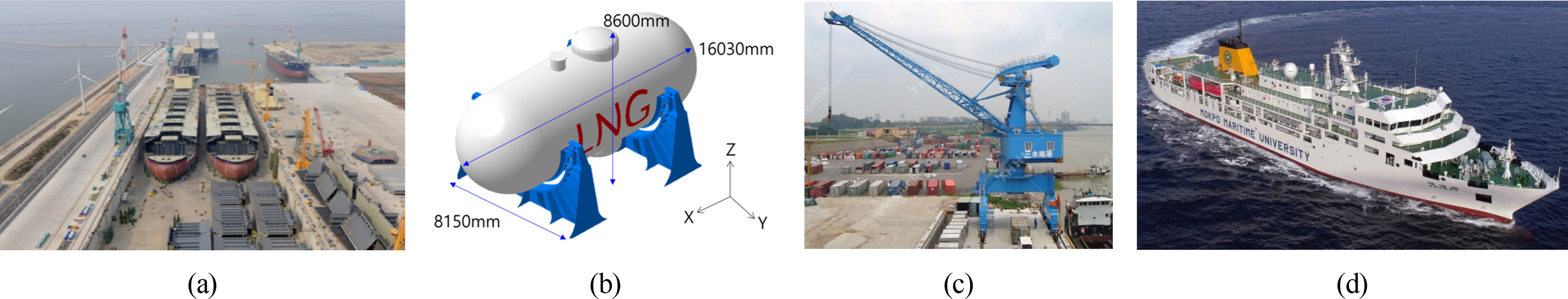
The scenario postulated in this study is the process of erecting an LNG tank (Fig. 1(b)) in a dock (Fig. 1(a)) on the stern part of the ship named the Segeroho (Fig. 1(d)) using a crane shown in Fig. 1(c). Regarding the erection position of the LNG tank, considering the size of the tank, Fr. 4, C.L of the stern part of the shelter deck of the Segeroho was selected as the erection position (Fig. 2). The stern part of the boat deck of the Segeroho needed to be removed to erect the LNG tank. Therefore, the LNG tank erection process was carried out, where the stern part of the boat deck was removed before the LNG tank erection process.
3. Near Real-Time Erection Spatial Environment
Frequently, there are some dissimilarities between the design data and the existing structure of the ship waiting for the erection process for various reasons, such as a malfunction of fieldwork, changes in work scheduling, and the complexity of the work site. If the design data has low reliability, this results in frequent situations where erection is not carried out according to the erection plan because of structures not identified in the design data. Therefore, it is essential to obtain accurate design data.
This section describes the construction process of the near real-time spatial environment and a comparison of the design data and near real-time data. Regarding the near real-time data of the Segeroho, the simulation product in this study, a 3D-built model from a point cloud was obtained using broadband laser scanning. 3D modeling for the design data and resource model of the Segeroho was then performed based on the design drawing. The near real-time data and design data of the Segeroho, the product of this simulation, were then compared by comparing the models of near real-time data and design data through data matching. The data of the midship part Ōł╝ A.E, were reflected because the erection position of the LNG tank is the stern, half of the data. Fig. 3 outlines the construction process of the spatial environment.
3.1 Selection of the Laser Scanner and 3D Built-Model from Point Cloud
Laser scanning is a technology for measuring the shape of an object in the form of 3D coordinates or point cloud data by shooting laser beams onto the surface of an object and capturing the laser beams reflected to the scanner (Lee, 2021). Selecting a laser scanner using the optimal measurement method and considering factors, such as the measurement distance, the object size, scanning speed, and measurement accuracy, is essential for acquiring 3D data efficiently (Lee et al., 2007). This study used a Leica RTC 360 laser scanner (Fig. 3) as the measurement method. RTC 360 uses waveform digitizer (WFD) technology that allows fast, high-precision, and long-distance measurements (Kim, 2013). RTC 360 is a high-performance laser scanner with an accuracy of 1.9 mm at a distance of 10 m, a maximum measurement distance of 130 m, and a scan rate of up to 2 million points per second.
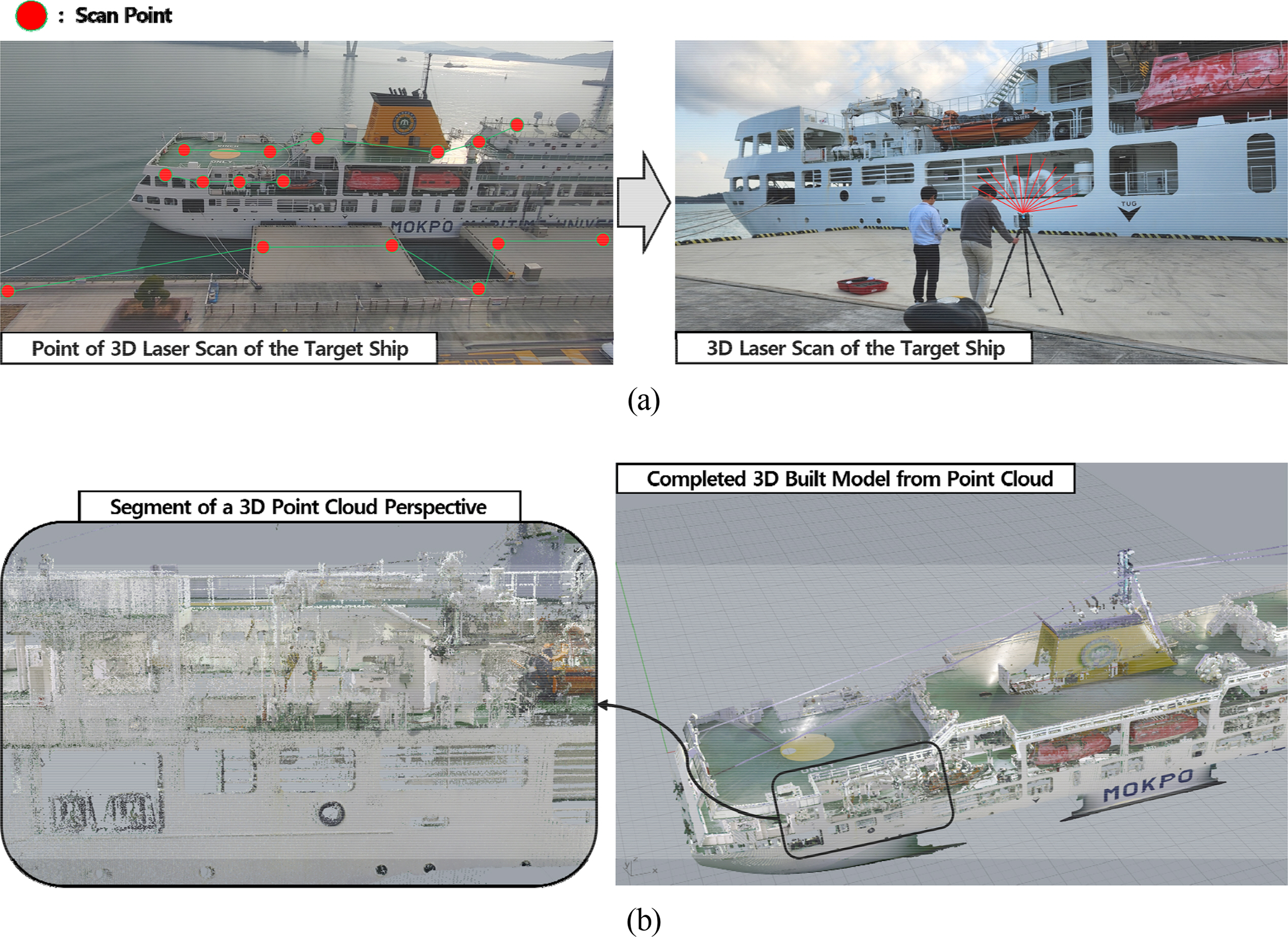
The process of acquiring near-time data using the selected laser scanner is as follows. Regarding the scope of measurement, the erection position was used as the reference position. The boat deck (Fr. 4 ŌĆō Fr. 28), the navigation bridge deck (Fr. 28 ŌĆō Fr. 76), the compass deck (FR. 76 ŌĆō Midship), the shelter deck (Fr. 2 ŌĆō Fr. 22), and the starboard surface (Looking port, Midship Ōł╝ A.E) were determined as the scope of measurement. According to the determined scope of measurement, scanning was performed at 20 points, including eight points on the stern of the shelter deck of the Segeroho, six points on the open deck, and six points on the starboard surface in the direction of the ship from the quay wall (Fig. 4(a)).
The acquired point cloud data contained 368,982,640 points, and it was necessary to perform postprocessing to remove the unnecessary points and perform data matching. First, the initial registration was performed using the automatic registration function of Leica Cyclone Register 360 (Leica Geosystems, n.d.) software. The unnecessary data were removed, and the second registration process was performed using Geomagic Design X (3D Systems, n.d.) software. As a result, a 3D-built model from a point cloud composed of 17,643,199 points was finally acquired (Fig. 4(b)).
The time needed to generate the Built-Model from Point Cloud is as follows. Scanning took one minute and 26 seconds per point, and postprocessing the total acquired data, including data matching and removing unnecessary data, took approximately three hours. Among the processes of generating the built model from the point cloud, raw data import required the most time, and the postprocessing time varied according to the specifications and performance of the computers used. Generating 3D design and modeling data required considerable time (Lee, 2018). As for the time needed for the 3D CAD (Computer-aided design) modeling of equipment, the 3D modeling of the main engine takes three days, and the 3D modeling of a single part takes approximately one hour (Kang et al., 2011). In this study, the 3D design model from the CAD of the Segeroho took approximately one week to generate. Therefore, if the scanning method presented in this study is used to acquire the latest ship data, it can reduce the time needed to generate 3D models compared to existing modeling methods.
3.2 3D Design-Model from CAD
A 3D design model from CAD was generated to compare the structural differences between the 3D-built model from the point cloud and the design data. This 3D design model was generated by 3D Modeling on the design data of the Segeroho using CATIA (Dassault Systems, n.d.), a type of CAD software.
3.3 Comparison of 3D Design-Model from CAD and 3D Built-Model from Point Cloud
The software used to construct the spatial environment was Unity 3D (Unity, n.d.), which is commonly used to develop simulations. Unity 3D enables users to develop simulations intuitively and simply because it supports various major platforms and technologies (Ki et al., 2020). In addition, Unity 3D permits simulation developers to achieve their desired results using diverse methods because it allows the asset developers to integrate various technologies (Lee, 2022).
The 3D-built model from the point cloud in Unity 3D was used by first rendering the data into a mesh using Geomagic Design X. After the data was exported into the FBX format, it was imported into Unity. The FBX extension is suitable for jointing objects, specifying collision areas, and constructing scripts because the elements of the hierarchical structure designed separately in CAD are separated into individual parts, and the classes used in CAD are applied. In addition, the scale of CAD software is applied consistently, and the pivot set for each part is also applied consistently.
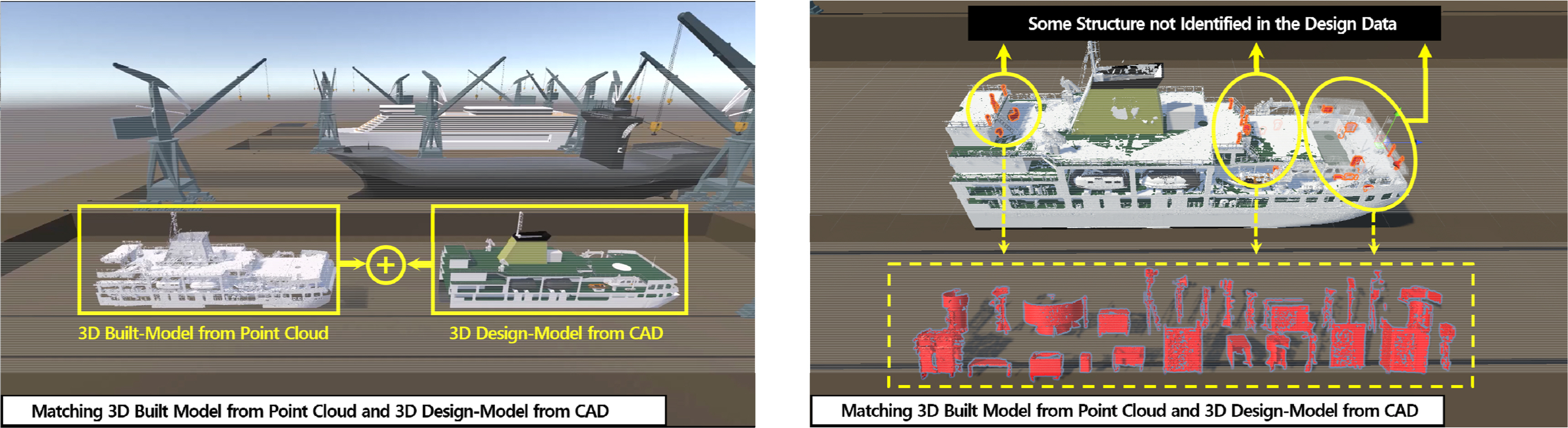
The 3D design model from CAD and the 3D-built model from the point cloud were compared by data matching on the Unity platform. As a result, 26 structures not identified in the 3D design model from CAD were identified from the 3D-built model from the point cloud. In Fig. 5, the red shapes represent the structures not identified in the 3D design model from CAD. These structures not identified in the design data are risk factors predictive of inference and collisions in the erection process. Section 4 presents the simulation process conducted by reflecting near real-time data to examine the impact of the risk factors on the erection process.
4. Improved Erection Process Simulation
This section describes the process of conducting the erection process simulation that was improved compared to existing simulations. This simulation was carried out by applying the spatial environment to the erection process plan established based on the jib crane loading manual and the design data of the Segeroho. Generally, an erection process plan is established according to design data based on the crane loading manual. Suppose the erection is performed according to the erection plan based on the design data. In that case, interference or a collision can occur due to structures not identified in the 3D design model from CAD but identified from the 3D-built model from the point cloud. Therefore, Section 4.1 presents an overview of the system of the inference and collision risk identification function generated by simulation to verify the erection process in advance for the reasons mentioned above (Fig. 6).
4.1 Overview of the Improved Erection Process Simulation System
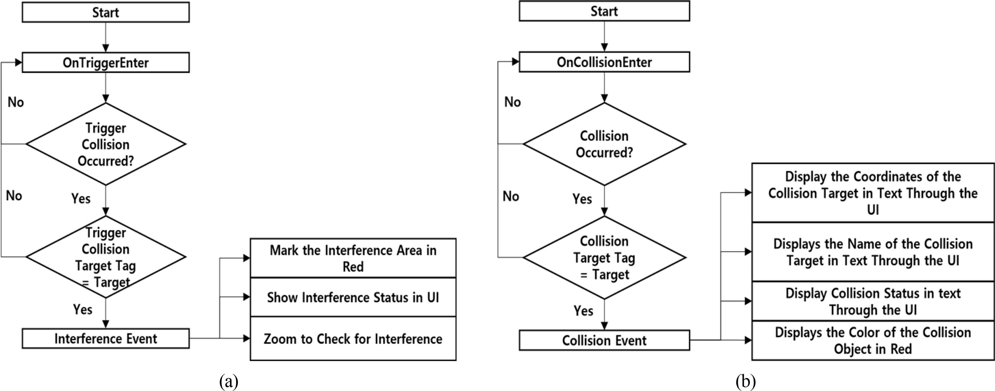
The physical effects were reflected in the spatial environment using C# Script and components, such as Collider, Rigidbody, and Joint, constructed through the NVIDIA PhysX engine (NVIDIA, n.d.) on the Unity 3D platform. An example of the functions generated through the spatial environment is identifying the risks for interference and collisions when a loading object is erected. First, interference refers to the existence of a structure that interferes with the movement of objects with a radius of motion, such as a crane. The radius of motion for each dynamic object on the ship was represented in the spatial environment to make it possible to check the presence of interference structures or the occurrence of interference. In addition, the spatial environment was constructed in such a way that the radius of motion of each dynamic object will be displayed in red to confirm the occurrence of interference visually when there is a structure within the radius of motion. Furthermore, the presence or absence of interference is displayed in the message window through the User Interface (UI), as shown in (Fig. 7(a).
The collision check function was designed to detect the collision of objects using the Collider component. In addition, through C# Script, it was designed to allow the visual identification of the occurrence of collisions between objects. In Fig. 7(b), the position of collision occurrence is indicated in red, and the collision status, the name of the collision object, and the location coordinates of the collision occurrence position are displayed in the message window through the UI.
4.2 Improved Erection Process Simulation ŌĆō Occurrence of Interference
In the near real-time erection process, there was interference with the working radius of the deck crane mounted on the stern part of the shelter deck before the LNG tank erection process began, as shown in Fig. 8(a). When interference occurred, the silhouette of the LNG tank appeared on the expected LNG tank erection position, and the working radius of the deck crane was activated. Hence, it was possible to identify the interference visually. Suppose the erection process is done without taking measures to resolve the inference problem. In that case, there is a limitation on the rotation angle of the deck crane mounted on the stern when LNG tank erection is performed. Consequently, if the deck crane overrotates within the limited range, it collides with the LNG tank. Fig. 8(b) shows the result of removing the interference structure to prevent interference with the operation of the deck crane before erecting the LNG tank.
4.3 Improved Erection Process Simulation ŌĆō Occurrence of Collision
The LNG tank erection process is performed as follows. First, the job crane rotates in the direction of where the LNG tank is located, and the tank is loaded after it is hooked to the crane. Next, the crane rotates toward the erection position, moving to the erection position with the LNG tank hooked to the crane. The crane is matched with the erection position in the horizontal distance. As the jib angle increases, the LNG tank is located on the vertical line of the erection position. Finally, the LNG tank is lowered and placed on the erection position, as shown in Fig. 9.
As a result of the simulation of the LNG tank erection process, through the 3D-built model from the point cloud, a collision occurred because two outdoor units among the structures were not identified in the 3D design model from CAD while the LNG tank was lowered on the erection position. These results showed that the LNG tank erection process necessitates the removal or relocation of structures, potentially causing collisions before the erection process. Fig. 9 shows the erection simulation process.
5. Conclusions
In this study, the spatial environment of the complex and highly variable erection process was constructed based on point cloud data by reflecting near real-time product data. In addition, a case study through improved erection process simulation was conducted based on the near real-time erection spatial environment. A comparison of the 3D built model from the point cloud with the 3D design model from CAD revealed 26 structures not identified previously in the 3D design model from CAD that were identified from the 3D built model from the point cloud. A simulation-based case study of the near real-time erection process was conducted based on Unity 3D to assess the impact of the structures not identified in the design data on the erection process. Through the verification of improved erection process simulation, interference occurred with the operation of the deck crane when an LNG tank was installed. A collision occurred when the LNG tank erection process was performed because of two outdoor units not previously identified in the 3D design model from CAD. This simulation case analysis verified the necessity of the relocation process for structures potentially causing interference or a collision. On the other hand, modifications to the jib crane loading manual, such as avoiding hazardous objects, were unnecessary.
In the block erection process, checking and identifying the risks for such interference and collisions is imperative. If any interference occurs during the erection process, it frequently leads to a situation where it is necessary to solve the problem with a loading object hooked onto a crane. Otherwise, the loading object must be moved again back to the original position. In addition, interference and collisions occurring in the block erection process may also lead to human accidents. Consequently, additional operations, including renewal operations, extend the time for the dock and affect the overall production schedule. In this way, accidents may cause quality deterioration and adversely affect the trust relationship with the ship owners due to problems, such as project delays.
The simulation in this study requires professional simulation engineers and expensive hardware and software. Nevertheless, as shipbuilding projects are generally carried out as a series of large-scale projects, the developed simulation is expected to contribute to acquiring up-to-date shipbuilding data and prevent process delays and serious industrial accidents.