
1. Introduction
In the design of submarines, frequent reviews are conducted regarding the hydrodynamic characteristics acting on the hull. A review of the hydrodynamic characteristics may include speed performance, maneuverability, and exceptional purpose performance. Generally, shipyards and research institutions worldwide have accumulated data (model tests, sea trials, and numerical analysis) based on their technology, research, development, and experience in surface ships for an extended period. These data are used frequently in the initial and detailed design of surface ships. On the other hand, in the case of submarines, unlike in surface ships, only a minimal amount of model test data, sea trial data, and numerical analysis data can be relied upon. This situation is also characterized by significantly reduced accessibility. Furthermore, in the case of submarines, the maneuvering performance in underwater operation is mentioned as an important factor closely related to submarine construction. In particular, submarines require considering the maneuvering performance for six degrees of freedom (DOF) of the hull, which makes it more challenging to deal with than maneuvering surface ships.
Thus far, the performance estimation of submarine maneuverability has followed the same procedure (using the mathematical model of maneuvering motion based on captive model tests) as that used in surface ships, but the complexity of the procedure must be considered as the degree of freedom of the considered maneuvering increases.
On the other hand, a representative method of estimating maneuvering performance using the six degrees of freedom (hereinafter 6DOF) maneuvering mathematical model proposed by Gertler and Hagen (1967) and Feldman (1979) is to use the mathematical model-based methods for submarine maneuvering. Generally, in methods based on mathematical models, it is essential to obtain hydrodynamic derivatives, which are the hydrodynamic forces included in the mathematical model. In the case of submarines, it is also essential to obtain hydrodynamic forces acting on the hull using the same approach. Several methods of captive model tests, theoretical calculations, and empirical equations are used to obtain hydrodynamic derivatives that act on the hull during submarine maneuvering. On the other hand, captive model tests are mainly used for submarines. Nevertheless, these mathematical model-based maneuvering performance estimation methods are mainly for the 6DOF motion of the general submarine (hereafter normal motion), and it is difficult to apply them to emergency rising motion, one of the special maneuvers of submarines (hereafter excessive motion).
Generally, the mathematical models used to represent the hydrodynamic forces included in the equations of motion of a submarine in normal motion use Taylor's third-order approximation expression for a multivariate function with the motion states of a submarine as variables. These mathematical models are represented considering the accuracy and complexity of the equations, based on the assumption that submarine motion is not excessive. On the other hand, the assumption that submarine motion is not excessive is no longer valid, and Taylor's third-order approximation expression is no longer valid when the submarine performs low-speed or emergency maneuvers. Hence, if the terms of Taylor's approximation are extended to higher-order terms of the third order, the expression for the hydrodynamic forces becomes more complex, and the expression becomes even more complicated because the six-degrees-of-freedom motion must be considered. Therefore, studies have been conducted to represent hydrodynamic forces more concisely and reflect physical phenomena more rigorously. Hooft (1994) proposed a mathematical model that separates the hydrodynamic forces acting on the surface ship hull into linear and nonlinear terms and expresses the linear term based on slender body theory and the nonlinear term based on cross-flow drag based on the drag coefficient when the yaw angle is 90°. Bohlmann (1990) proposed a similar mathematical model proposed by Hooft for submarines. Shin et al. (2005) applied the same mathematical model as Bohlmann (1990) to submarines and validated the proposed mathematical model using theoretical equations for various submarines. Furthermore, Watt (2007) proposed a mathematical model that includes a Fourier series form of a multivariable function representing the hydrodynamic forces acting on a submarine when it moves at various angles based on a mathematical model similar to Gertler and Hargen (1976). Park et al. (2017) proposed a mathematical model that uses a polynomial function form of a multivariable function instead of a Fourier series form, similar to Watt (2007) model. Although the mathematical models proposed by Watt (2007) and Park et al. (2017) considered the behavior of submarines at various angles, they have limitations in that they do not consider large-angle motions.
Karasuno et al. (1991, 1992) proposed a new mathematical model for maneuvering a fishing vessel with a large drift maneuvering motion. The mathematical model suggested by Karasuno et al. is composed of fluid dynamic coefficients commonly used in aerodynamics (such as lift and drag coefficients) and cross-flow drag coefficients. Karasuno et al.'s research presents results that can express various maneuvering motions, including forward, backward, and large turning motions of a fishing vessel. The mathematical model proposed by Karasuno et al. does not use complex coefficients and has the advantage of incorporating physical meaning into the coefficients and describing turning motion using the hydrodynamic coefficients obtained from the drift motion. Therefore, this study examined the applicability of the mathematical model proposed by Karasuno et al. for a submarine and proposed a mathematical model applicable to a submarine. Chapter 2 introduces the 6DOF maneuvering equations of a submarine and the hydrodynamic mathematical model proposed by Karasuno. In Chapter 3, large drift angle and angle of attack calculations are performed on horizontal and vertical planes using computational fluid dynamics (CFD) for the MARIN BB2. Chapter 4 confirms the utility of the mathematical model by deriving the hydrodynamic coefficients proposed by Karasuno et al. from these calculations and comparing them with the calculation results of the existing Taylor 3rd approximation formula.
2. Mathematical Model for the Maneuvering Motion of Submarine
2.1 6DOF Maneuvering Equation of Motion for Submarine
Assuming a submarine as a rigid body and symmetric about the x-z plane, the 6DOF maneuvering equation of motion for the submarine can be expressed as Eqs. (1)–(6) using Newton's equations of motion, with a coordinate system fixed to a submarine as shown in Fig. 1 (Sohn et al., 2006).
Each force and moment includes the hull, propeller, elevator and stern plane, and hydrostatic forces, and the superscripts ⦁ and G indicate differentiation with respect to time and the center of gravity, respectively. As mentioned in the introduction, the forces and moments on the left-hand side of Eqs. (1)–(6) can be expressed using the equations proposed by Gertler and Hargen (1967) or Kim et al. (2021). As stated previously, this study proposes a mathematical model using a new approach for these external forces and validates the model accuracy. This study investigated the applicability of Karasuno et al.'s mathematical model to submarines.
2.2 Physical-Based Hydrodynamic Model (Karasuno Model)
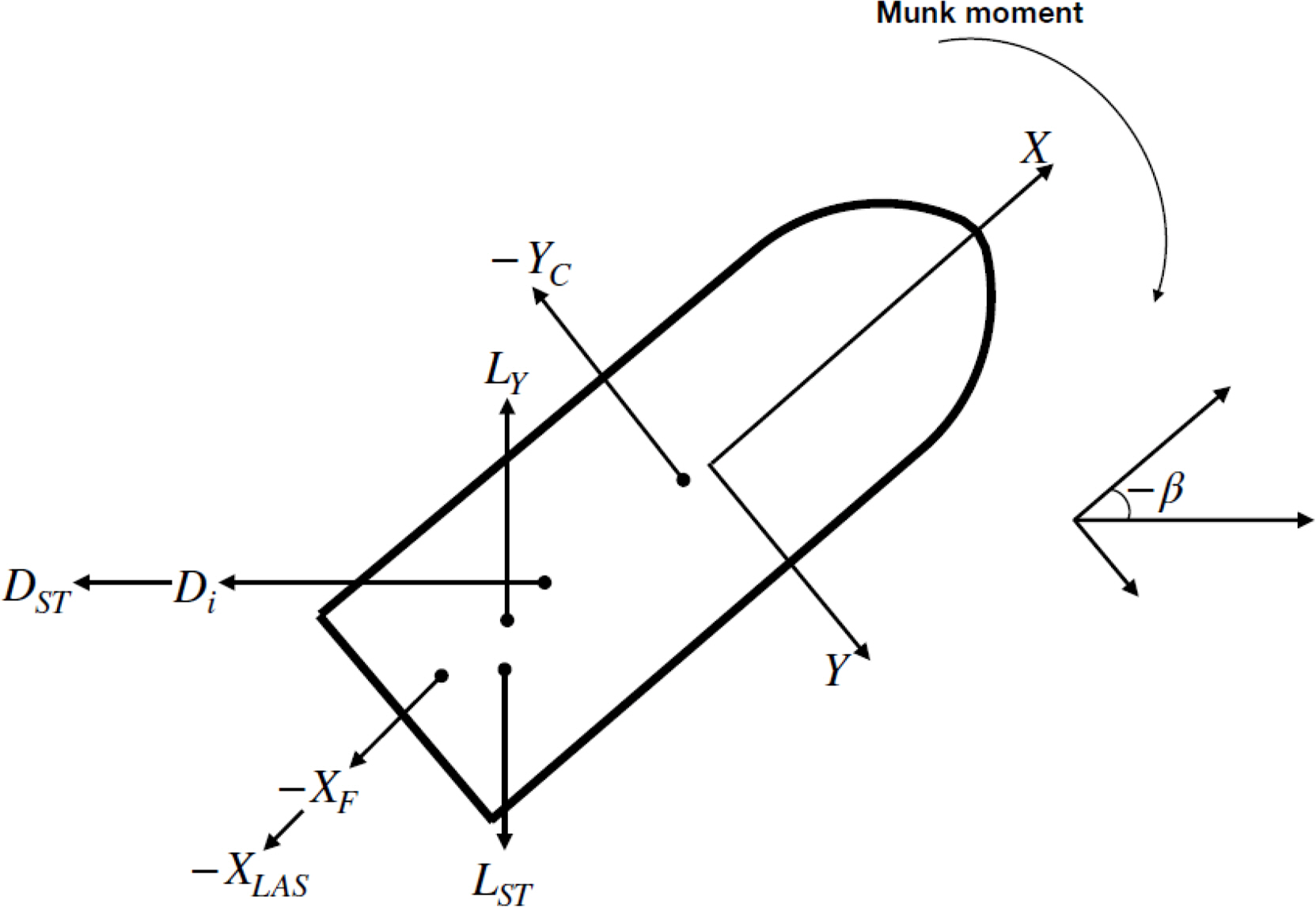
Karasuno et al. separated the hydrodynamic forces acting on the hull in a situation where the submarine is moving (Fig. 2) into seven elements: Munk moment, lift, drag, cross-flow lift, cross-flow drag, frictional force, and correction force due to the stall.
Table 1 lists the seven elements that make up the mathematical model proposed by Karasuno et al. (1991, 1992)
In the formulae presented in Table 1, the symbol ′ represents a non-dimensional value; u and v represent the longitudinal velocity and the transverse velocity, respectively; U represents the total speed of the submarine; m and m′ represent mass and transverse addedmass, respectively; Lpp represents the length of the hull; ΔCL and ΔCDi represent the lift and drag correction coefficients due to stall, respectively; CL and CDi represent the lift and drag coefficients; CD90 represents the cross-flow drag coefficient; CF is the friction coefficient; m0 and m1 represent the area and first moment of the lateral projection of the body center, respectively. Using the seven elements in Table 1, the force and moment acting on the body can be expressed as Eqs. (7)–(9).
Here, where l′v0 and l′i0 represent the lever moment’s lever due tobecause the lift and drag forces, respectively, and (1+p⋅cos2β) is a term introduced to correct the cross-flow drag. Eqs. (7)–(9) represents the hydrodynamic forces and moment acting on the hull, and to use it in the equations of motion, it is necessary to obtain the seven elements that make upin Eqs. (7)–(9) to use it in the equations of motion. To obtain each element, Karasuno et al. proposed an analysis procedure using a fishing vessel as the target ship to obtain each element, as described listed in Table 2.
3. Numerical Analysis
3.1 Numerical Method
Chapter 2 introduced the physics-based mathematical model proposed by Karasuno et al. to estimate the hydrodynamic forces for the six degrees of freedom motion of a submarine at large angles of attack in detail. As previously mentioned, model tests or numerical calculations are necessary to obtain the hydrodynamic forces suggested in the Karasuno model. For submarines, however, facilities capable of performing model tests for large drift angle motions (or large angle of attack motion) are rare compared to surface ships. Furthermore, this study presents a methodology for reconstructing the hydrodynamic forces based on the proposed mathematical model using information obtained from model tests or numerical calculations. Therefore, this study performed numerical analysis using CFD instead of model tests. The commercial CFD software STAR-CCM+ was used for the numerical analysis, and Table 3 lists the basic numerical techniques used in this study. In addition, all forces and moments in this study were non-dimensionalized using Eq. (10).
3.2 Calculation Results for Horizontal Static Drift and Vertical Static Angle of Attack Motion
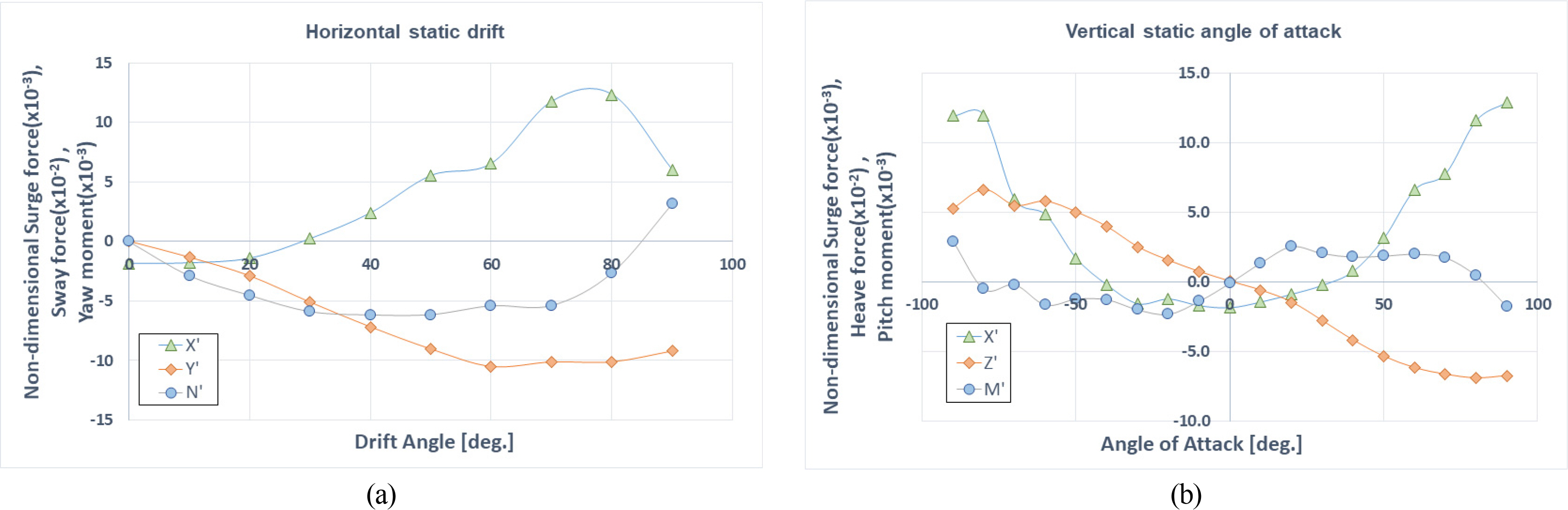
Fig. 4(a) shows the calculation results for the horizontal static motion. The longitudinal force (in green), lateral force (in orange), and pitching moment (in blue) increase Aas the yaw angle increases according to Fig. 4. On the other hand, the longitudinal and lateral forces decreased around yaw angles of 75° and 60°. The pitching moment reached a maximum around the yaw angle of 50° and then decreased. In the case of horizontal static motion, only the yaw angles from 0° to 90° were calculated because the submarine shape is symmetric, and they did not consider the astern motion. The lateral force decreased due to the strong backflow caused by the flow separation from the submarine sail and hull after the yaw angle of 60°, and the pitching moment also decreased due to the same effect (Choi, 2023).
Fig. 4(b) shows the calculation results for the vertical static angle of attack motion. As shown in Fig. 4, the longitudinal force (in green), vertical force (in orange), and pitching moment (in blue) increase as the angle of attack increases. On the other hand, the vertical force decreased around the trim angle of 80°. The pitching moment reached its maximum around the angle attack of 20° before decreasing slightly between 20° and 50° and then increased again around 60° before decreasing. In addition, complex flow patterns were formed for a negative angle of attack as the flow passing through the hull encounters the sail, leading to different characteristics than the positive angle of attack and showing asymmetry in force and moment (Choi, 2023).
4. Discussion
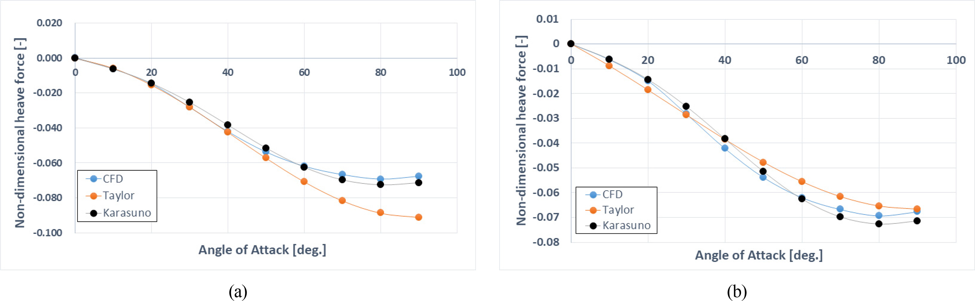
Fig. 5 compares the reconstructed vertical force (Karasuno, black) using the hydrodynamic coefficients obtained from the procedure described in Table 2 and the vertical force obtained by Taylor third-order approximation (Z =Zw′⋅w′+Zwww′⋅w′3) with the CFD result (blue). In Fig. 5(a), the coefficients for constructing Taylor third-order approximation (Taylor, orange) were obtained from the CFD values in the range of negative angles (α = 0°–20°) and used to predict the large angle values. In Fig. 5(b), the coefficients were obtained from the CFD values in the range of the large angles (α = 0°–90°) and used to predict large angle values.
First, the reconstructed lateral force using the Karasuno model generally reproduced the CFD results well. On the other hand, the mathematical model using Taylor third-order approximation showed relatively good results up to an angle of attack of 50°, but it failed to reproduce the CFD values from an angle of attack of 60° and above. Moreover, although the mathematical model using Taylor third-order approximation generally reflects the trends of the CFD results, a significant difference was observed between the two in the entire range, as shown in Fig. 5(b). The order of the hydrodynamic coefficients in the approximation equation could be increased to more than a fifth-order term to reduce the error of the mathematical model using Taylor approximation. As mentioned in the introduction, introducing higher-order terms complicates the maneuvering equations of the submarine.
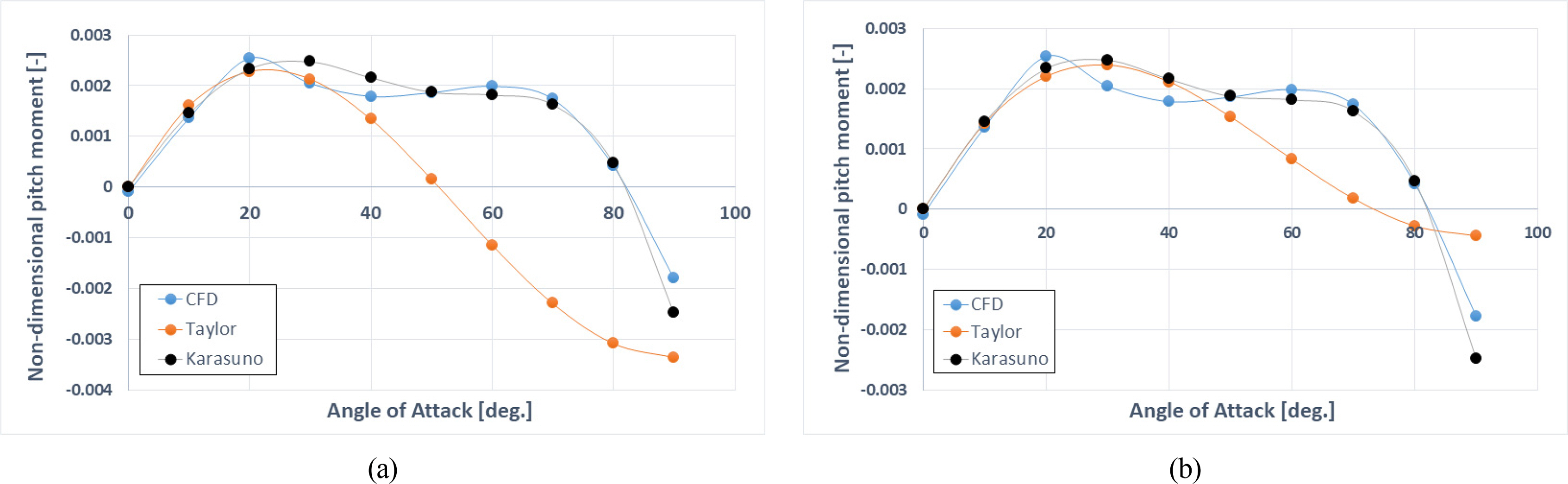
Fig. 6 shows the comparison result between the reconstructed pitch moment (Karasuno, black) using the lift coefficients obtained from CFD calculations by the procedure described in Table 2 as mentioned above, and the pitch moment (Taylor, orange) obtained by Taylor third-order approximation (M =Mw′⋅w′ +Mwww′⋅w′3), compared to the CFD results (blue). Among these results, Fig. 6(a) shows the reconstructed pitch moment over the range of angles of attack (hereafter AOA) (α = 0°–90°) using the lift coefficient obtained from the CFD values in the AOA range (α = 0°–20°) in the analysis of vertical force., and Fig. 6(b) shows the reconstructed pitch moment at the large AOA range (α = 0°–90°) using the lift coefficient obtained from the CFD values in the large AOA range (α = 0°–90°).
The Karasuno model relatively well reconstructed the CFD results over the entire range (Fig. 6), while the Taylor third-order approximation showed good results up to 30° AOA in Fig. 6(a), but showed significant differences from the CFD results at the large AOA (Fig. 6(b)), similar to the results in the vertical force. Similar results are obtained for the lateral force and yaw moment caused by the large drift motion (Choi, 2023), indicating the utility of the Karasuno model proposed in this study for the large drift/AOA motion.
5. Modified Karasuno Model
In this study, the applicability of the mathematical model proposed by Karasuno et al. was confirmed using CFD with a submarine as a target ship. In particular, it is proposed as expressed in Eqs. (11) and (12) below.
Horizontal motion
X ′ = C L h h ′ u ′ v ′ 2 − C D i h h ′ u ′ 3 v ′ 2 − ( Δ C L h h ′ u ′ v ′ 2 − C D i h h ′ u ′ 3 v ′ 2 ) − C L A S h h ′ v ′ 2 − C F h h ′ | u ′ | u ′ + C L h v ′ u ′ w ′ 2 − C D i h v ′ u ′ 3 w ′ 2 − ( Δ C L h v ′ u ′ w ′ 2 − C D i h v ′ u ′ 3 w ′ 2 ) − C L A S h v ′ w ′ 2 − C F h v ′ | u ′ | u ′ Y ′ = C L h h ′ u ′ 2 v ′ − C D i h h ′ u ′ 2 v ′ 3 − C D 90 h h m 0 ′ ( 1 + cos 2 β ) v ′ 3 + C L h v ′ u ′ 2 w ′ − C D i h v ′ u ′ 2 w ′ 3 − C D 90 h v m 0 ′ ( 1 + cos 2 α ) w ′ 3 N ′ = ( m x ′ − m y ′ ) u ′ v ′ − C L h h ′ l v 0 h h ′ u ′ 2 v ′ − C D i h h ′ l i 0 h h ′ u ′ 2 v ′ 3 − C D 90 h h m 1 ′ ( 1 + cos 2 β ) v ′ 3 − C L h v ′ l v 0 h v ′ u ′ 2 w ′ − C D i h v ′ l i 0 h v ′ u ′ 2 w ′ 3 − C D 90 h v m 1 ′ ( 1 + cos 2 α ) w ′ 3
(11)
Vertical motion
X ′ = C L v v ′ u ′ w ′ 2 − C D i v v ′ u ′ 3 w ′ 2 − ( Δ C L v v ′ u ′ w ′ 2 − C D i v v ′ u ′ 3 w ′ 2 ) − C L A S v v ′ w ′ 2 − C F v v ′ | u ′ | u ′ + C L v h ′ u ′ v ′ 2 − C D i v h ′ u ′ 3 v ′ 2 − ( Δ C L v h ′ u ′ v ′ 2 − C D i v h ′ u ′ 3 v ′ 2 ) − C L A S v h ′ v ′ 2 − C F v h ′ | u ′ | u ′ Z ′ = C L v ′ u ′ 2 w ′ − C D i v ′ u ′ 2 w ′ 3 − C D 90 v m 0 ′ ( 1 + cos 2 α ) w ′ 3 + C L v h ′ u ′ 2 v ′ − C D i v h ′ u ′ 2 v ′ 3 − C D 90 v h m 0 ′ ( 1 + cos 2 α ) v ′ 3 M ′ = ( m x ′ − m z ′ ) u ′ w ′ − C L v ′ l v 0 v ′ u ′ 2 w ′ − C D i v ′ l i 0 v ′ u ′ 2 w ′ 3 − C D 90 v m 1 ′ ( 1 + cos 2 α ) w ′ 3 − C L v h ′ l v 0 v h ′ u ′ 2 v ′ − C D i v h ′ l i 0 v h ′ u ′ 2 w ′ 3 − C D 90 v h m 1 ′ ( 1 + cos 2 α ) v ′ 3
(12)
The superscript, hh, vv, hv and vh in Eqs. (11) and (12) represent the direction of the forces acting on the submarine, which depend on the direction of motion. Therefore, the superscripts hh and vv denote “forces acting in the same direction as the motion”. In contrast, the superscript vh denotes “forces acting in the vertical direction due to horizontal motionmotion,” and hv denotes “forces acting in the horizontal direction due to vertical motion”. From their meanings, they represent the coupling term. The coupling terms that have the superscripts and can be ignored in the normal maneuvering motion of a submarine, but these coupling terms cannot be ignored in the special maneuvering motion, such as emergency rising or low-speed operation. In the present study, these coupling terms were ignored because of the lack of proven evidence. Table 6 lists all hydrodynamic coefficients obtained from CFD calculation.
6. Conclusions
This study applied the mathematical model proposed by Karasuno et al. to the maneuvering motion of a submarine using CFD to confirm its applicability. In particular, the forces and moments acting on the submarine during significant drift and angle of attack motions were calculated and used to derive the hydrodynamic coefficients used in the Karasuno model. A mathematical model based on Taylor's third-order approximation was used to reconstruct the hydrodynamic force acting on the submarine during large drift and transverse motions. The results were compared with those obtained using Karasuno's physically-based mathematical model. The following results were obtained:
(1) It was confirmed that the Karasuno model could obtain more accurate results than the Taylor third-order approximation-based mathematical model in estimating the hydrodynamic forces acting on the submarine during large drift and angle of attack motions.
(2) To use the Taylor approximation-based mathematical model to estimate the hydrodynamic forces acting on the submarine hull during a large drift and angle of attack motions, it is necessary to extend the order of the approximation equation to higher-order terms.
Nevertheless, more research will be needed to introduce additional terms for the hydrodynamic forces acting in the vertical plane direction during horizontal motion and in the horizontal plane direction during vertical motion. Second, while this study focused only on large drift and angle of attack motions, further research on the rotational and turning motions of submarines will be necessary.